Introduction to aluminum PCBs
Aluminum printed circuit boards (PCBs) are a specialized type of PCB made using aluminum metal as the base substrate instead of the more common FR-4 fiberglass material.
Aluminum PCBs were first developed in the 1970s and have seen growing use in recent years for applications requiring high thermal performance, weight savings, and durability.
This article provides an in-depth look at aluminum PCB technology – how they are constructed, their benefits and limitations, typical applications exploiting their advantages, considerations in design and assembly, and other key information on utilizing aluminum PCBs.
How are aluminum PCBs constructed?
Aluminum PCBs have the following basic construction and composition:
- Base substrate is made from flat aluminum metal sheets typically 0.8mm to 3mm thick depending on application needs. Alloys include 5052, 6061, and 7075 grades optimized for PCB fabrication.
- A chemical conversion coating is applied to the aluminum surface to prepare it for further processing steps. This improves adhesion and corrosion resistance.
- Dielectric layers like polyimide are laminated onto the substrate to provide electrical insulation. Vias and through holes pierce the dielectric layers.
- Copper tracks are formed on the dielectric layers to create the circuitry pattern. Standard subtractive or additive photolithography processes are used.
- Components are mounted onto the board surface with standard SMT assembly processes. Special considerations are required in some cases.
- Organic solderability preservatives (OSP), immersion silver, or other finishes protect exposed copper from oxidation.
- Silkscreen and nomenclature are printed to identify components and contacts. Conformal coatings, stiffeners, or heatsinks may also be added.
The end result is a rigid, metal core PCB with the desired circuitry that takes advantage of aluminum’s thermal and mechanical properties.
What are the benefits of using aluminum PCBs?
Some key benefits of aluminum PCBs include:
- Excellent thermal performance – Aluminum has high thermal conductivity, dissipating heat efficiently from components. This enables high power applications.
- Light weight – With a density 1/3 that of copper, aluminum PCBs are lighter, reducing product weight. This is advantageous in aerospace, automotive and portable designs.
- Strength and rigidity – Aluminum has high tensile strength, providing rugged, durable PCBs that resist warping and withstand vibration and shocks.
- Low CTE – Aluminum PCBs have a coefficient of thermal expansion (CTE) close to that of silicon chips. This reduces stresses from CTE mismatch.
- Electrically non-conductive – The aluminum core is insulated from the circuitry layers, avoiding electrical shorts. FR-4 fiberglass in contrast is conductive.
- Handles high currents – Aluminum PCBs can carry high electrical currents necessary in power electronics due to the metal core.
- Cost effective – The raw material cost of aluminum is lower than exotic metal core substrates, making aluminum PCBs more economical.
These characteristics make aluminum PCBs suitable for demanding, high reliability and extreme environment applications where FR-4 boards may not suffice.
What are the limitations and challenges with aluminum PCBs?
There are some limitations and considerations when working with aluminum PCB technology:
- Thermal management – The metal core requires vias, thermal pads, and heatsinks to conduct heat away from components effectively. Thermal analyses are important.
- Fabrication challenges – Chemical treatments, surface prep, lamination processes, and drilling/routing aluminum are more complex compared to standard FR-4 PCBs.
- Component mounting – Thermal mismatches between components, pads, and aluminum substrate require analysis. Mechanical stresses require appropriate fastener selection.
- Mixed metal corrosion – Aluminum is anodic to copper and can corrode galvanically. Electrical isolation and coatings are essential.
- EMI shielding – The conductive aluminum core can impair radiation performance which may necessitate shielding layers.
- Repairability – It is harder to rework and repair components on aluminum boards compared to FR-4.
With careful design and assembly methods however, these limitations can be appropriately managed.
What are the typical applications and uses of aluminum PCBs?
Some common applications that utilize aluminum PCB technology include:
- Power electronics – IGBTs, power diodes, converters and other power devices benefit from aluminum PCB thermal performance.
- Automotive electronics – Demanding under-hood environments exploit aluminum PCB capabilities for engine control, transmission, and sensing boards.
- Avionics and aerospace – Rugged aluminum PCBs withstand vibration while cutting weight in guidance systems and avionics.
- LED lighting – High brightness LEDs use aluminum PCBs as heatsinks and to operate at higher currents than FR-4 boards allow.
- Industrial – Motor drives, robotics, machine tools and test equipment leverage aluminum PCB strengths.
- Military and defense – Radar, guidance systems, avionics and vetronics for armored vehicles utilize aluminum or metal core PCBs.
- High frequency RF – Microwave and mmWave circuits benefit from the consistent dielectric properties.
Any application with extreme thermal, mechanical or electrical demands can potentially gain advantages from choosing aluminum PCB technology.
What are the essential design considerations for aluminum PCBs?
Key design aspects when developing a circuit on aluminum PCBs include:
Thermal management – Use thermal vias, extra layers, and thermal pads under hot components to conduct heat into aluminum substrate. Perform thermal simulation.
Mechanical mounting – Account for thermal expansion, shock/vibration loads. Use insulated standoffs, flex mounts, and retention hardware.
Component selection – Choose components rated for high temperatures aluminum PCBs can reach. Ensure CTE mismatch won’t cause stresses.
Board finishes – Immersion silver, hard gold, or OSP coatings help minimize risk of galvanic corrosion between aluminum and copper.
Soldering – Use solderable finishes for component pads. Leaded or lead-free solders both work. Match footprint, paste volumes and profile to the metal core.
EMI/grounding – Include EMI shielding layers in stackup. Provide multiple ground plane layers connected by vias to aluminum core.
Layout considerations – Provide isolation keepouts between aluminum and traces for safety. Watch for bottlenecks in power distribution.
With careful design, analysis, validation, and testing, high performance, reliable aluminum PCBs can be successfully developed.
What are the key fabrication steps to make aluminum PCBs?
Fabricating aluminum PCBs involves several specialized steps:
- Surface preparation – Abrasion and chemical etching cleans and micro-roughens aluminum surface for bonding dielectric layers
- Conversion coating – Anodization or chemical chromate process creates insulating oxide layer for corrosion protection
- Dielectric lamination – High pressure and temperature bonds dielectric layers like polyimide to core under vacuum
- Drilling – Carbide and diamond tooling cuts through-holes and vias in the aluminum substrate
- Metallization – Sputtered copper creates seed layer for electroplating thick copper circuit layers with standard lithography
- Component mounting – Reflow soldering attaches SMD components. Adhesives assemble some components
- Protection – Immersion silver or OSP coated on exposed copper surfaces prevents oxidation
- Testing – Electrical testing validates connectivity. Thermal shock, vibration and life testing ensures reliability
- Finishing – Silkscreen, solder mask, edge connectors, and other final finishes are applied
Aluminum PCB fabrication requires specialized processes and tooling but enables exploiting aluminum’s capabilities.
What key challenges are faced in assembling components onto aluminum PCBs?
Some assembly challenges specific to aluminum PCB technology include:
- ThermalMismatch – Differences in coefficient of thermal expansion between chip package and aluminum substrate induces stresses. Underfill helps.
- Soldering – High thermal conductivity of aluminum requires profile adjustments so solder joints form properly.
- Mechanical fastening – Bolts, clamps and adhesive bonding is needed for large components to reduce loads on solder.
- RF shielding – Gaskets, conductive elastomers or spring contacts maintain shielding at seams between aluminum and component shields.
- Cleaning – Aluminum surfaces are sensitive to chemicals and solvents requiring special handling. Plasma or laser cleaning may be used.
- Rework – Removing and replacing components on aluminum PCBs is more difficult requiring hot gas tools.
- Conformal coating – Coatings must withstand high temperatures and thermal cycling that aluminum PCBs experience.
With the right assembly processes dialed in and component selection, the challenges of assembling aluminum PCBs can be overcome.
How are components mounted and connected on aluminum PCBs?
There are several approaches to mounting and connecting components to aluminum PCBs:
- SMD soldering – Most SMT components are soldered to PCB pads like standard PCB assembly. Solderable PCB finishes are required.
- Through-hole soldering – Leaded components are soldered into plated through holes. Match solder melting point to aluminum PCB operating temperatures.
- Adhesive bonding – Large aluminum components like heatsinks are secured with thermally conductive epoxy adhesives. Provides high bond strength.
- Mechanical fastening – Standoffs, spacers, screws, clamps and spring clips retain large components while reducing loads on solder joints.
- Conductive elastomer contacts – Provide reliable connections between aluminum substrate and metal component housings while allowing for differential expansion and contraction.
- Wire bonding – Fine aluminum or gold wires are ultrasonically wedge bonded for electrical connections requiring flexibility and high current capacity.
A combination of soldering, adhesives, fasteners and specialized interconnect methods are used to assemble electronics onto aluminum PCB platforms.
What kinds of connectors work with aluminum PCBs?
Some types of electrical connectors suitable for use with aluminum PCBs include:
- Solder mount – Through-hole pins allow connectors to be soldered for mechanical strength and electrical connection. High temperature solders are used.
- Press-fit – Connectors with compliant pins press-fit into plated through holes in the PCB for gas-tight, reliable connections without soldering.
- Crimp style – Insulated terminals are crimped to wires secured into metal housings that bolt to the PCB edge. Provides flexibility.
- Board-edge style – Connectors clamp onto the PCB edge exposing copper pads on the board edge for soldering or press-fit.
- Flexible ribbon – Flexible Kapton/copper laminate ribbon cables plug into connectors mounted on the PCB to link boards.
- RF connectors – SMA, SMB, SMP and other coaxial RF connectors are mounted with mechanical hardware and soldered for microwave applications.
- Custom adapters – Custom machined adapters allow integrating standard connectors to aluminum PCBs accounting for thermal expansion.
The connector style can be selected to optimally address mechanical robustness, thermal stresses, vibration resistance, electrical needs, and other requirements of the application.
What key thermal factors need to be considered when designing aluminum PCBs?
Thermal design considerations for aluminum PCBs include:
- Component power dissipation – Determine max heat flux from each component needing cooling to set heatsink requirements.
- Heatsink interface – Use thermal interface materials and pressure mounts for efficient heat transfer from components to heatsink.
- Aluminum substrate thickness – Thicker aluminum layers provide lower thermal resistance and greater heat spreading.
- Thermal vias – High density copper filled thermal vias conduct heat between layers and to aluminum substrate.
- Thermal pads – Exposed copper pads under hot components conduct heat into PCB layers. Match size to max component heat flux.
- Internal copper layers – Additional copper layers aid lateral heat spreading on PCB.
- High conductivity dielectrics – Dielectrics like polyimide, aluminum nitride and silicones transfer heat better than standard FR-4.
- Thermal analyses – Perform thermal simulation, testing and verification to confirm design cooling performance.
Proactively addressing thermal requirements in the design prevents hot spots and ensures the aluminum PCB can effectively cool all electronics.
What types of testing are performed to validate aluminum PCB designs?
Testing performed on aluminum PCB prototypes includes:
| Test | Purpose |
|---|---|
| In-circuit testing | Validates electrical connectivity between nodes matches circuit netlist |
| Functional testing | Confirms PCB operates correctly and meets functional requirements |
| HASS and HALT | Accelerated stress screening and testing to uncover design weaknesses and early failures |
| Vibration and shock | Ensures PCB can withstand mechanical vibration and shocks during use |
| Thermal shock and cycling | Evaluates robustness to rapid or cyclic temperature changes the PCB will experience |
| Temperature/humidity bias testing | Assesses operation and reliability under hot/humid environmental conditions |
| EMC/EMI testing | Validates PCB meets immunity and emissions requirements |
| Climatic testing | Exposes PCB to range of operating temperatures and humidity levels |
| Fluid exposure | Confirm resistance to exposure to fluids like fuels, hydraulic oil and cleaning chemicals |
| Salt spray | Demonstrates the environmental protection provided by PCB coatings and conformal layers |
Extensive validation testing demonstrates reliable, robust performance and a suitable lifetime when deployed in the field.
What types of tools are used to fabricate aluminum PCBs?
Specialized tools used in aluminum PCB fabrication include:
- Laser drills and routers equipped with diamond cutters to machine through holes and cut outs in the aluminum substrate
- Diamond saws and carbide routers for precision cutting of the aluminum boards
- Vacuum presses for laminating dielectric and thermal layers onto the aluminum at high pressures
- Wave, convection and vapor phase soldering tools optimized for aluminum PCB assembly
- Ovens and belts customized for baking and curing layers during lamination at elevated temperatures
- Anodization tanks and chemical baths for surface treatments to prepare the aluminum for lamination
- Precision online metrology tools to validate etch depth, hole size, lamination thickness and other critical process parameters
- Microsectioning and microscopy tools to inspect plated hole quality, layer cross-sections and interface integrity
- X-ray imaging systems to check for hidden voids, delamination defects and proper inner layer alignment
The combination of customized fabrication tools and expertise in working with aluminum enables cost-effective production of high quality aluminum PCBs.
How should aluminum PCBs be handled and protected during shipping and assembly?
To prevent damage during transit and assembly, aluminum PCBs should be:
- Separately packed wrapped in ESD-safe pink poly bags sealed to keep out moisture and debris
- Inserted into rigid shelves or compartments inside card board boxes to avoid bending
- Immobilized inside shipping boxes with Styrofoam peanuts or air pillows to prevent shifting and rubbing
- Cushioned on both sides with soft foam or rubber pads to absorb impacts
- Clearly labeled as aluminum PCBs requiring delicate handling with arrows showing proper orientation
- Shipped via land or air methods with movement/shock indicators that trigger if preset thresholds are exceeded
- Unpacked in ESD-safe areas and immediately dry stored in controlled conditions after receipt
- Protected with end caps and handled by edges to avoid scratching conductive traces or damaging components
Careful protective packaging and handling measures are essential to ensure fragile aluminum PCBs are not damaged during transport, storage or assembly processing.
What are some emerging trends in aluminum PCB technology?
Emerging developments in aluminum PCB technology include:
- Thermally conductive dielectrics – Diamond, ceramic and graphene infused dielectrics for 5-10X better thermal conductivity than standard materials
- Direct bond copper (DBC) – Copper foil directly bonded to aluminum removes need for separate dielectric layer
- Thin dielectric layers – Ultra-thin dielectrics down to 25-50um enable compact, multilayer aluminum PCBs
- Bare die mounting – Power semiconductors directly soldered to aluminum substrate for superior thermal management
- SiC and GaN devices – Wide bandgap semiconductors enable lighter, more powerful PCBs for aviation and space
- Aluminum on aluminum – Dielectric-less PCBs with aluminum traces on aluminum substrate for high frequency antenna arrays
- Heat pipes and cold plates – Integrated heat pipe and liquid cold plate technologies actively cool aluminum PCBs
- Metal 3D printing – Additive manufacturing directly prints aluminum PCB substrates and enclosures from CAD models
Continued materials and process improvements will expand applications and capabilities for aluminum PCB technology.
Aluminum PCBs FAQ
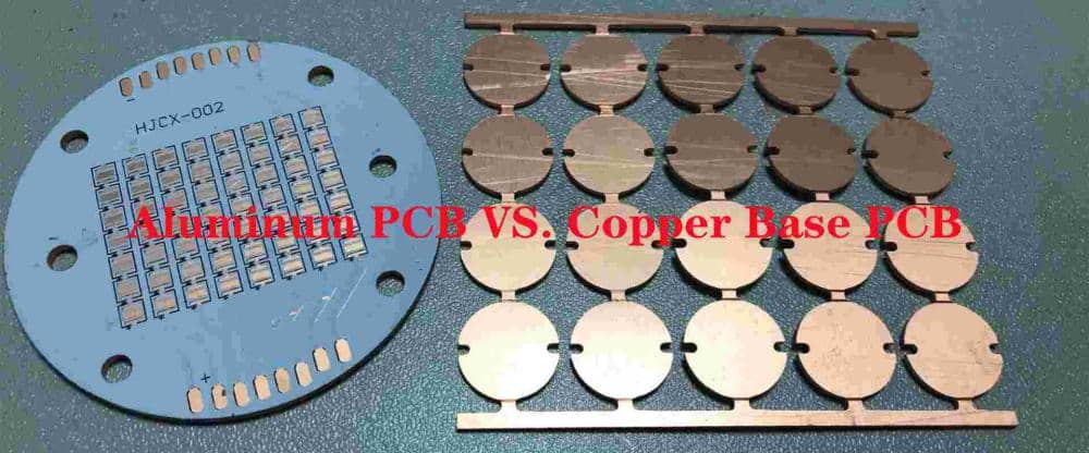
What are some key differences between aluminum and standard FR-4 PCBs?
FR-4 is an electrical insulator while aluminum is thermally conductive but electrically isolating when anodized. Aluminum has higher strength and stiffness but weighs less. It withstands heat and cold extremes better but requires different assembly processes.
Can components be mounted on both sides of aluminum PCBs?
Yes, aluminum PCBs can be double-sided, providing front and backside SMT mounting like FR-4 boards. Vias connect traces on both sides. Mixing component types can help manage board heating.
Do aluminum PCBs cost more than standard PCBs?
The fabrication process for aluminum PCBs is more complex so they cost approximately 20-30% more than equivalently sized FR-4 boards for medium volume orders. The metal material cost difference is minor.


Leave a Reply