Introduction to the TIP31C Transistor
The TIP31C is a high-power NPN transistor designed for switching and amplification purposes. It is part of the TIP series of transistors, which are known for their robustness and reliability. The TIP31C is capable of handling significant current and voltage levels, making it suitable for a wide range of applications, including motor drives, power supplies, and audio amplifiers.
Key Features of the TIP31C
- High current handling capability (up to 3A)
- High voltage rating (up to 100V)
- High power dissipation (up to 40W)
- Fast switching speed
- TO-220 package
TIP31C Pinout Configuration
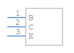
To effectively use the TIP31C transistor, it is crucial to understand its Pinout Configuration. The TIP31C comes in a TO-220 package, which has three pins: the collector, base, and emitter.
Pin Arrangement
The pin arrangement of the TIP31C is as follows:
| Pin Number | Pin Name | Description |
|---|---|---|
| 1 | Base | Controls the flow of current between the collector and emitter |
| 2 | Collector | Positive terminal of the transistor |
| 3 | Emitter | Negative terminal of the transistor |
It is important to note that the pin arrangement may vary depending on the manufacturer and the specific variant of the TIP31C. Always refer to the datasheet provided by the manufacturer for the exact pinout configuration.
Identifying the Pins
To identify the pins of the TIP31C, you can refer to the following methods:
-
Package Marking: The TIP31C package often has the part number and pin labels printed on its surface. Look for the “TIP31C” marking and the corresponding pin labels (B for base, C for collector, and E for emitter).
-
Datasheet: Consult the datasheet provided by the manufacturer for a detailed diagram of the pinout configuration. The datasheet will also provide information on the package dimensions and the recommended PCB layout.
-
Multimeter: If the package marking is unclear or absent, you can use a multimeter to identify the pins. Set the multimeter to the diode test mode and follow these steps:
- Connect the red probe to the base pin and the black probe to the emitter pin. The multimeter should show a voltage drop of approximately 0.7V, indicating a forward-biased PN junction.
- Connect the red probe to the collector pin and the black probe to the emitter pin. The multimeter should show a higher voltage drop (e.g., 1.2V) compared to the base-emitter junction.

Electrical Characteristics of the TIP31C
To design circuits using the TIP31C transistor effectively, it is essential to understand its electrical characteristics. The following table summarizes the key electrical parameters of the TIP31C:
| Parameter | Symbol | Value | Unit |
|---|---|---|---|
| Collector-Emitter Voltage | VCEO | 100 | V |
| Collector-Base Voltage | VCBO | 100 | V |
| Emitter-Base Voltage | VEBO | 5 | V |
| Collector Current (Continuous) | IC | 3 | A |
| Collector Current (Peak) | ICM | 5 | A |
| Base Current (Continuous) | IB | 1 | A |
| Power Dissipation | PD | 40 | W |
| Operating Temperature Range | TJ | -65 to 150 | °C |
These values represent the maximum ratings and should not be exceeded to ensure the safe and reliable operation of the TIP31C transistor. It is recommended to refer to the datasheet for more detailed information on the electrical characteristics, including graphs and performance curves.

TIP31C as a Switch
One of the primary applications of the TIP31C transistor is as a switch. When used as a switch, the TIP31C can control the flow of current through a load, such as a motor, relay, or LED. The base pin is used to control the switching action, while the collector and emitter pins are connected in series with the load.
Basic Switching Circuit
A basic switching circuit using the TIP31C transistor can be constructed as follows:
            +---------------+
            |               |
            |              +-+
            |              | | Load
            |              +-+
            |               |
            |               |
          +-+-+           +-+-+
          |   |           |   |
  +-------+   +-----------+   +------+
  |       |                          |
  |      B|                          |
+-+       |                          |
|         |                          |
| Control |                          |
| Signal  |                          |
|         |C                        E|
+-+       |                          |
  |       |                          |
  +-------+                          |
          |   TIP31C                 |
          +-+---------+--------------+
            |         |
            |         |
            +---------+
In this circuit, the load is connected between the collector and the positive power supply, while the emitter is connected to ground. The control signal is applied to the base pin through a current-limiting resistor. When the control signal is high (e.g., 5V), the transistor turns on, allowing current to flow through the load. When the control signal is low (e.g., 0V), the transistor turns off, and no current flows through the load.
Calculating the Base Resistor Value
To ensure proper switching operation, it is important to select an appropriate value for the base resistor. The base resistor limits the current flowing into the base pin and prevents damage to the transistor. The value of the base resistor can be calculated using the following formula:
R_B = (V_CC - V_BE) / I_B
Where:
– R_B is the base resistor value in ohms (Ω)
– V_CC is the control signal voltage in volts (V)
– V_BE is the base-emitter voltage drop (typically 0.7V for silicon transistors)
– I_B is the desired base current in amperes (A)
For example, if the control signal voltage is 5V and the desired base current is 10mA, the base resistor value can be calculated as follows:
R_B = (5V - 0.7V) / 0.01A
    = 430Ω
In this case, a standard resistor value of 430Ω or 470Ω can be used for the base resistor.

TIP31C as an Amplifier
Another common application of the TIP31C transistor is as an amplifier. When used as an amplifier, the TIP31C can increase the power or voltage of an input signal. The base pin is used to control the amplification, while the collector and emitter pins are connected to the load and power supply, respectively.
Common Emitter Amplifier
A common emitter amplifier configuration using the TIP31C transistor can be constructed as follows:
         +---------------------+
         |                     |
         |                    +-+
         |                    | | R_L
         |                    +-+
         |                     |
       +-+-+                 +-+-+
       |   |                 |   |
     +-+   +---+---+---+---+-+   +-----+
     |       |   |   |   |             |
     |      R_B  R_E C_E |             |
+-+  |       |           |             |
| |  |       |           |             |
| | C_in     |           |             |
| |  |       |B          |E           C|
+-+  +-------+           |             |
     |               TIP31C            |
     |                   |             |
    GND                 GND           +-+
                                      | | R_C
                                      +-+
                                       |
                                       |
                                      +-+
                                      | | V_CC
                                      +-+
In this circuit, the input signal is applied to the base pin through a coupling capacitor (C_in) and a base resistor (R_B). The emitter is connected to ground through an emitter resistor (R_E) and a bypass capacitor (C_E). The collector is connected to the positive power supply (V_CC) through a collector resistor (R_C) and the load (R_L).
The values of the components in the amplifier circuit depend on factors such as the desired gain, bandwidth, and input/output impedance. Proper design considerations should be made to ensure stable operation and prevent distortion.
TIP31C in Power Supplies
The TIP31C transistor is often used in power supply circuits due to its high current and voltage handling capabilities. It can be employed in various power supply topologies, such as linear regulators and switching regulators.
Basic Linear Regulator
A basic linear regulator using the TIP31C transistor can be constructed as follows:
         +----------+
         |          |
        +-+        +-+
        | |        | |
        | |        | |
        | |        | |
        +-+        +-+
         |   C_in   |
         |          |
         |         +-+
         |         | | R_L
         |         +-+
         |          |
       +-+-+      +-+-+
       |   |      |   |
     +-+   +------+   +------+
     |                       |
     |                       |
     |            TIP31C     |
     |                       |
     |                       |
     |                       |
     |B                     C|
     |                       |
     |                       |
     |                      E|
     +-------+-------+-------+
             |       |
             |       |
            R_B     R_E
             |       |
             |       |
            GND     GND
In this circuit, the unregulated input voltage is applied to the collector of the TIP31C through a filter capacitor (C_in). The base is connected to a voltage reference (not shown) through a base resistor (R_B). The emitter is connected to the output load (R_L) and a feedback resistor (R_E). The TIP31C acts as a variable resistor, adjusting its resistance to maintain a constant output voltage across the load.
The values of the components in the linear regulator circuit depend on the desired output voltage, maximum load current, and input voltage range. Proper heat sinking and thermal management should be considered to prevent overheating of the TIP31C transistor.
Frequently Asked Questions (FAQ)
- What is the maximum collector current rating of the TIP31C transistor?
-
The maximum continuous collector current rating of the TIP31C is 3A. However, it can handle peak collector currents up to 5A for short durations.
-
Can the TIP31C be used as a switch for inductive loads, such as motors or relays?
-
Yes, the TIP31C is suitable for switching inductive loads. However, it is important to use appropriate protection measures, such as flyback diodes or Snubber Circuits, to prevent voltage spikes and protect the transistor from damage.
-
What is the power dissipation rating of the TIP31C transistor?
-
The TIP31C has a maximum power dissipation rating of 40W. However, this value is dependent on factors such as the ambient temperature and the heat sinking arrangements. Proper thermal management is crucial to ensure reliable operation and prevent overheating.
-
How do I determine the appropriate heatsink for the TIP31C transistor?
-
The selection of a suitable heatsink depends on the power dissipation requirements and the thermal resistance of the heatsink. The thermal resistance of the heatsink should be low enough to maintain the junction temperature of the TIP31C within its specified limits. Heatsink manufacturers often provide thermal resistance data and selection guides to assist in choosing the appropriate heatsink.
-
Can the TIP31C be directly connected to a microcontroller or digital logic circuit for switching purposes?
- No, the TIP31C cannot be directly connected to a microcontroller or digital logic circuit. The base current required to switch the TIP31C is typically higher than what a microcontroller or digital logic circuit can provide. A suitable driver circuit, such as a transistor or MOSFET driver, should be used to interface the microcontroller or digital logic with the TIP31C.
Conclusion
The TIP31C is a versatile and widely used NPN transistor that finds applications in switching, amplification, and power supply circuits. Understanding its pinout configuration, electrical characteristics, and application-specific considerations is essential for designing reliable and efficient electronic systems.
By following proper design guidelines, such as selecting appropriate component values, implementing protection measures, and ensuring adequate heat dissipation, the TIP31C transistor can be effectively utilized in a wide range of projects. Whether you are a hobbyist, a student, or a professional engineer, mastering the technical knowledge of the TIP31C transistor will enhance your ability to create robust and high-performance electronic circuits.


Leave a Reply