What is a Solder Bridge?
A solder bridge, also known as a solder short, is an unintentional connection between two or more soldered points on a printed circuit board (PCB) that should not be connected. This unwanted connection is typically caused by excess solder during the soldering process, resulting in a conductive link between adjacent pads, pins, or traces. Solder bridges can lead to various issues, such as short circuits, malfunctions, and even permanent damage to electronic components.
Types of Solder Bridges
There are two main types of solder bridges:
-
Pad-to-Pad Solder Bridge: This type of solder bridge occurs when excess solder forms a connection between two adjacent pads on a PCB. It is the most common type of solder bridge and can be caused by using too much solder, incorrect soldering technique, or improper component placement.
-
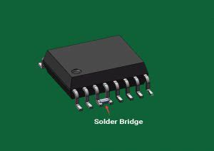
Pin-to-Pin Solder Bridge: This type of solder bridge happens when excess solder connects two or more pins of a component, such as an integrated circuit (IC) or connector. Pin-to-pin solder bridges can be more challenging to identify and repair due to the small spacing between pins and the potential difficulty in accessing the affected area.
Causes of Solder Bridges
Several factors can contribute to the formation of solder bridges:
-
Excessive Solder: Applying too much solder during the soldering process is a common cause of solder bridges. When excess solder is present, it can flow and create unintended connections between adjacent pads or pins.
-
Incorrect Soldering Technique: Poor soldering technique, such as holding the soldering iron on a joint for too long or using incorrect tip size or temperature, can lead to solder bridges. Improper technique can cause the solder to spread beyond the intended area and create unwanted connections.
-
Improper Component Placement: Misaligned or improperly placed components can cause their leads or pins to be too close to adjacent pads, increasing the risk of solder bridges forming during the soldering process.
-
Inadequate PCB Design: Poor PCB design, such as insufficient spacing between pads or traces, can make it more likely for solder bridges to occur. Proper PCB layout and design guidelines should be followed to minimize the risk of solder bridges.
Identifying Solder Bridges
Identifying solder bridges is crucial for ensuring the proper functioning of electronic devices. There are several methods to detect solder bridges:
Visual Inspection
The most straightforward method to identify solder bridges is through visual inspection. This can be done with the naked eye or by using magnification tools such as a magnifying glass or microscope. When examining a PCB, look for the following signs of solder bridges:
- Excess solder connecting adjacent pads or pins
- Solder that appears to have flowed beyond the intended area
- Shiny or reflective connections between pads or pins that should not be connected
Continuity Testing
Continuity testing is an effective method to detect solder bridges that may not be visible through visual inspection. This method involves using a multimeter to check for electrical continuity between points that should not be connected. To perform continuity testing:
- Set your multimeter to the continuity or resistance mode.
- Place one probe on a pad or pin and the other probe on an adjacent pad or pin that should not be connected.
- If the multimeter indicates continuity (a beep or low resistance reading), a solder bridge is present.
Repeat this process for all potentially affected pads and pins to identify any solder bridges.
Functional Testing
Functional testing involves powering on the electronic device and observing its behavior to detect any issues caused by solder bridges. This method can help identify solder bridges that may not be detectable through visual inspection or continuity testing. Signs of solder bridges during functional testing include:
- Unexpected behavior or malfunctions
- Short circuits or overheating
- Incorrect voltage readings
- Failure to power on or initialize properly
If any of these issues are observed, further investigation and troubleshooting should be conducted to identify and resolve potential solder bridges.

Preventing Solder Bridges
Preventing solder bridges is essential for ensuring the reliability and functionality of electronic devices. Here are some best practices to minimize the occurrence of solder bridges:
-
Use the Right Amount of Solder: Apply the appropriate amount of solder to each joint. Excess solder increases the risk of bridges forming, while insufficient solder can lead to weak or incomplete connections. Practice and experience will help you gauge the proper amount of solder needed for different types of joints.
-
Maintain Proper Soldering Technique: Use the correct soldering iron tip size and temperature for the job. Apply heat to the pad and lead simultaneously, allowing the solder to flow naturally. Avoid holding the soldering iron on the joint for too long, as this can cause the solder to spread and create bridges.
-
Ensure Proper Component Placement: Double-check component placement before soldering to ensure that leads and pins are correctly aligned with their respective pads. Use tweezers or placement tools to position components accurately and maintain appropriate spacing between adjacent pads and pins.
-
Follow PCB Design Guidelines: When designing PCBs, adhere to recommended design guidelines for pad and trace spacing. Ensure that there is sufficient clearance between adjacent pads and traces to minimize the risk of solder bridges forming. Consider using solder mask to cover areas where solder bridges are likely to occur.
-
Use Flux Appropriately: Flux helps the solder flow evenly and adhere to the surfaces being joined. However, excessive flux can cause the solder to spread beyond the intended area and create bridges. Use flux sparingly and choose the appropriate type of flux for your application.
-
Clean the PCB: After soldering, clean the PCB to remove any flux residue or debris that may contribute to the formation of solder bridges. Use appropriate cleaning solutions, such as isopropyl alcohol, and a soft brush or lint-free cloth to clean the board thoroughly.
By following these best practices and maintaining a clean and organized work environment, you can significantly reduce the occurrence of solder bridges and improve the overall quality of your soldering work.

Repairing Solder Bridges
When a solder bridge is identified, it must be repaired to ensure the proper functioning of the electronic device. There are several methods to repair solder bridges, depending on the severity and location of the bridge.
Solder Wick Method
The solder wick method involves using a copper braid, also known as desoldering braid or solder wick, to remove excess solder from the bridged area. To use this method:
- Place the solder wick over the solder bridge.
- Apply the soldering iron tip to the top of the solder wick, allowing the heat to transfer through the wick and melt the excess solder.
- As the solder melts, it will be wicked away by the copper braid through capillary action.
- Remove the soldering iron and solder wick, and inspect the area to ensure that the solder bridge has been successfully removed.
Solder Sucker Method
A solder sucker, also known as a desoldering pump, is a manual vacuum pump designed to remove molten solder from a joint. To repair a solder bridge using a solder sucker:
- Heat the solder bridge with the soldering iron until the solder melts.
- Quickly position the solder sucker over the molten solder and press the plunger to create suction.
- The molten solder will be drawn into the solder sucker, removing it from the bridged area.
- Inspect the area to confirm that the solder bridge has been eliminated.
Soldering Iron Method
In some cases, a solder bridge can be removed using just a soldering iron. This method works best for small solder bridges or when the excess solder can be easily manipulated. To use this method:
- Heat the solder bridge with the soldering iron until the solder melts.
- Gently drag the soldering iron tip through the molten solder, pulling the excess solder away from the bridged area.
- Remove the soldering iron and allow the solder to cool and solidify.
- Inspect the area to ensure that the solder bridge has been successfully removed.
After repairing a solder bridge, it is essential to clean the area thoroughly and re-inspect the joint to confirm that the repair was successful and no new bridges have formed.

FAQs
-
What are the consequences of solder bridges?
Solder bridges can cause short circuits, leading to malfunctions, overheating, or even permanent damage to electronic components. They can also result in incorrect voltage readings and signal interference, compromising the overall performance and reliability of the electronic device. -
Can solder bridges be detected by automated inspection systems?
Yes, automated optical inspection (AOI) systems and X-ray inspection systems can detect solder bridges during the manufacturing process. These systems use advanced imaging techniques and algorithms to identify defects, including solder bridges, on PCBs and assemblies. -
Are there any specific tools designed for removing solder bridges?
Yes, there are specialized tools designed for removing solder bridges, such as solder bridge removers or rework stations. These tools often combine heating elements with suction or vacuum capabilities to efficiently remove excess solder from bridged areas. -
Can solder bridges occur in surface-mount technology (SMT) assemblies?
Yes, solder bridges can occur in SMT assemblies, particularly when components are placed too close together or when excessive solder paste is applied during the reflow soldering process. Proper PCB design, stencil selection, and process control are essential to minimize the risk of solder bridges in SMT assemblies. -
How can I improve my soldering skills to prevent solder bridges?
To improve your soldering skills and prevent solder bridges, consider the following: - Practice regularly on scrap PCBs or practice kits
- Attend soldering workshops or training courses
- Study proper soldering techniques and best practices
- Invest in high-quality soldering tools and equipment
- Maintain a clean and organized work environment
- Regularly inspect your work for potential defects and make necessary adjustments to your technique
By understanding the causes, identification methods, prevention techniques, and repair strategies for solder bridges, you can significantly improve the quality and reliability of your electronic assemblies.
| Method | Advantages | Disadvantages |
|---|---|---|
| Visual Inspection | – Quick and easy – Requires no additional tools |
– May miss small or hidden bridges – Depends on operator skill and attention to detail |
| Continuity Testing | – Detects bridges not visible to the naked eye – Provides objective measurements |
– Requires a multimeter – May be time-consuming for larger assemblies |
| Functional Testing | – Detects bridges that affect device performance – Verifies overall functionality |
– May not identify the specific location of the bridge – Some bridges may not cause immediate issues |
By combining these methods and following best practices for prevention and repair, you can effectively identify and resolve solder bridges in your electronic assemblies, ensuring optimal performance and reliability.


Leave a Reply