What are Rigid Flexible PCBs?
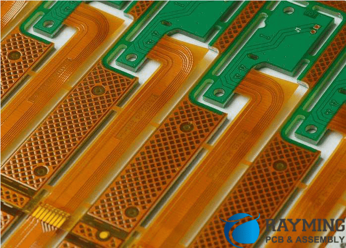
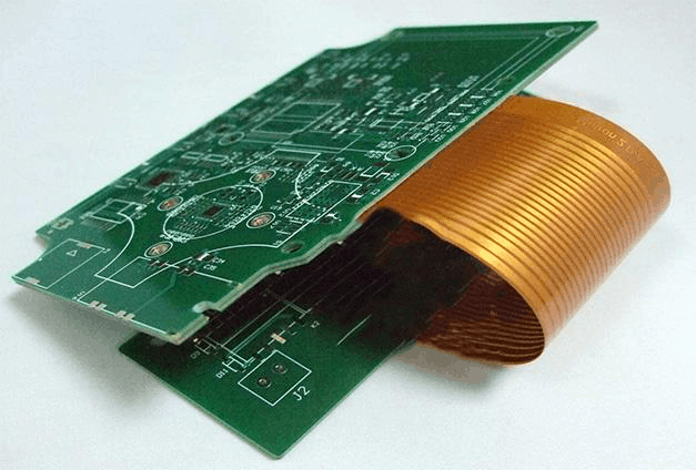
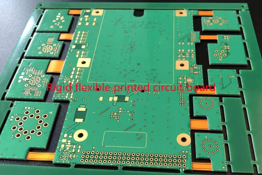
A rigid flexible printed circuit board (rigid flex PCB or flex-rigid PCB) is a hybrid printed circuit board (PCB) that consists of rigid and flexible substrates laminated together. The rigid sections provide mechanical support while the flexible sections allow dynamic flexing, bending or folding of the PCB.
Rigid-flex PCBs provide solutions for electronic devices that require:
- Dynamic flexing or bending during use (e.g. wearables, medical devices)
- Space savings and portability with the ability to fold or wrap the PCB
- Movable or hinged sections of a device
Rigid flex PCBs allow the integration of multiple rigid PCBs into a single assembly through flexible “jumpers” or connections. This eliminates connectors, enhances reliability and reduces overall product size.
Types of Rigid Flex PCBs
There are several design variations of rigid flex PCBs:
Multilayer Rigid Flex
Multilayer rigid flex combines 2 or more circuit layers with flexible dielectric layers to create flexible “jumpers” between multiple rigid sections. The most common type is 4-6 layer rigid flex.
Rigid Flex with Flexible Bends
This type integrates flexible bends between rigid sections to facilitate folding or bending of the PCB. The bends are made of flexible dielectric material with conductors.
Rigid Flex with Flexible Circuits
Here the rigid boards are interconnected by dedicated flexible circuits rather than just flexible bends. The flex circuits can have conductors and components.
Sculpted Rigid Flex
These PCBs have complex 3D shapes with flex dimensions tailored to product mechanics. They may have multiple flex layers laminated together.
Rigid vs Flexible Materials
The choice of rigid and flexible materials is a key design decision for rigid flex PCBs:
Rigid Substrate Materials
The rigid sections of the PCB typically use:
- FR-4: Flame retardant fiberglass reinforced epoxy laminate. Most common rigid PCB material.
- Polyimide: Provides higher temperature resistance than FR4. Used for high reliability applications.
- Aluminum or metal core: Enhances thermal conductivity for high power circuits.
- Other advanced dielectrics: For specialized mechanical or electrical needs.
Flexible Substrate Materials
Common flexible materials are:
- Polyimide: Standard flex circuit material, available in a range of thicknesses. Withstands bending and flexing.
- Polyester: Lower cost alternative to polyimide. Limited temperature range.
- PEEK: High temperature resistance above 150°C. Chemical resistant.
- Fluoropolymers: Extremely flexible even at low temps. Chemically inert.
- LCP: Liquid crystal polymer. Stable electrical performance under flexing.
Benefits of Rigid Flex PCBs
Rigid flexible PCBs offer several advantages over rigid PCBs:
- Space savings: Ability to fold and bend the PCB allows efficient use of space in compact devices. Removes need for external cables and connectors.
- Increased reliability: Elimination of connectors and reduced parts count through integration results in higher reliability.
- Improved manufacturability: Combining multiple PCB assemblies into a single rigid flex PCB simplifies manufacturing and assembly.
- Enhanced flexibility and movement: Dynamic sections of a product can be designed with flexible PCB sections.
- Light weighting: Rigid flex PCBs allow lighter and more portable product designs vs rigid PCBs.
- Design flexibility: Rigid flex allows three-dimensional PCB shaping to conform to product industrial design requirements.
Rigid Flex PCB Design Considerations
Designing a reliable rigid flex PCB requires attention to the following factors:
Layer Stack Up
The sequence of rigid and flexible layers requires careful planning, especially for high layer count boards. Avoiding flex-on-rigid interfaces enhances reliability.
Conductor Layout
Tracks between rigid sections should be properly routed across bends to avoid excessive stresses. Maintaining symmetry equalizes stresses.
Component Placement
Components at a rigid-flex junction may require special SMT pads or relief cutouts to prevent cracking. Larger components need to be on rigid sections.
Flex Bend Radii
Bend radius should exceed minimum levels specified for the flexible material to prevent conductor damage and cracks.
Copper Thickness
Thicker copper (2 oz +) is preferred on flex layers for durability. Annealing enhances flex life.
Stiffeners
Rigid stiffeners, frames or shields around flexible sections control bending and prevent unwanted flexing.
thermal management
Thermal vias, copper fills and other means are used to conduct heat across the length of the PCB.
Rigid Flex PCB Fabrication
Rigid flex PCB manufacturing involves specialized processes:
- Lamination: Alternating layers of rigid and flexible materials are laminated using high heat and pressure. Registration is critical.
- Imaging: Exposing the conductors requires advanced laser direct imaging (LDI) to handle varying board thicknesses.
- Etching: Etch compensation is used to achieve correct conductor widths across rigid and flex areas.
- Hole drilling: Mechanical and laser drilling with depth control creates vias across flex and rigid layers.
- Metal plating: Ensures plated through hole (PTH) reliability at transitions between rigid and flex.
- Solder mask: Liquid photoimageable (LPISM) solder mask enables coating uneven board surfaces.
- Final profiling: Precise routing, scoring and V-cut processes profile complex rigid flex board shapes.
Rigid flex PCBs require advanced manufacturing expertise and equipment to produce.
Applications of Rigid Flex PCBs
The unique properties of rigid flex PCBs make them suited for the following types of products:
Consumer Electronics
- Laptops, Ultrabooks: Interconnect motherboard and display
- Smartphones: Foldable phones, flex mounted antennas
- Wearables: Conform to curves and flex points on the body
- Digital cameras: Wrap around optics and mechanisms
Medical
- Hearing aids: Flex sections fit over ear
- Implants: Withstand dynamic bending of organs
- Wearable monitors: Attach to various body parts
Industrial
- Robotics: Arms, joints, end effectors
- Automation: Position sensors, machine vision systems
Automotive
- Advanced driver assist (ADAS): Sensor modules mounted on curved surfaces
- Hybrid/electric systems: High current rigid flex circuits
Aerospace/Military
- Missiles: Maneuverable airfoils and control surfaces
- UAVs: Wings, joints and movable camera gimbals
Key Considerations When Choosing a Rigid Flex Partner
Selecting the right PCB partner is crucial when designing rigid flex PCBs:
- Proven rigid flex expertise: Look for extensive experience with all varieties of multilayer rigid flex circuits.
- In-house engineering support: Partner should have rigid flex design experts to assist with layout, DFM and troubleshooting.
- Advanced manufacturing capabilities: Requires specialized equipment and processes to produce high-quality and reliable rigid flex PCBs.
- Quality certifications: Indicators of consistent production and reliability such as ISO 9001.
- Prototyping abilities: Ability to iteratively refine rigid flex designs through multiple prototype stages.
- Volume production: Scalable infrastructure to support transfer from prototyping to volume production.
- Reliable flex materials supply chain: Vetted network of flexible dielectric materials partners.
- Competitive pricing: Mature production yields supporting cost optimization.
Rigid Flex PCB Design and Fabrication FAQ
Here are answers to some frequently asked questions about rigid flex PCB design and manufacturing:
What are the minimum bend radii for common flexible PCB materials?
- Polyimide: 0.1mm
- Polyester: 0.15mm
- PEEK: 2-5mm
- LCP: 0.75mm
How many flex layers can be incorporated in a rigid flex PCB?
High layer count rigid flex PCBs can integrate up to 6-8 flex layers between rigid sections. The rigid layers are typically symmetrical outside the flex layers.
What are recommended SMT pad geometries for components crossing rigid-flex boundaries?
SMT pads spanning rigid-flex interfaces should use rectangular or oval shapes rather than square pads. Elongated pads reduce stresses.
What are some methods to ensure reliable plated through holes (PTH) across rigid and flex sections?
- Extra PTH wall thickness using direct metallization
- Annealed copper for flex layer PTHs
- Tented vias
- Filler collars around flex PTHs
How can conductors be protected against folding stresses on flexible PCB sections?
Common techniques include:
- Adhesive coversheets over flex conductors
- Conformal coatings on conductors
- U-shaped formations around bends
- Reinforcement rings around drill holes
How should heat dissipation be handled across the length of a rigid flex PCB?
Use of thermal vias, internal copper heat spreaders, and exposed copper pads/planes help conduct heat between rigid board sections through the flex layers.
Conclusion
Rigid flexible PCBs enable innovative packaging and integration of flexible circuits and multiple rigid boards into compact assemblies. With careful design considerations for the materials, layer stackup, conductor layout, component placement and bend radii, reliable multilayer rigid flex circuits can be manufactured successfully. Rigid flex PCB technology provides size, weight and reliability benefits in a vast range of electronics products spanning consumer, medical, automotive and aerospace market segments. Partnering with a flexible PCB company having certified expertise in cost-effective prototyping and volume production of multilayer rigid flex PCBs is key to successfully implementing and commercializing rigid flex PCB designs.


Leave a Reply