Introduction to Rigid FPCs
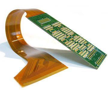
A flexible printed circuit (FPC) is a thin, lightweight circuit made from flexible insulating material with conductive traces etched or printed on one or both sides. FPCs allow connections between electronic components and devices even in environments where flexing or bending is required.
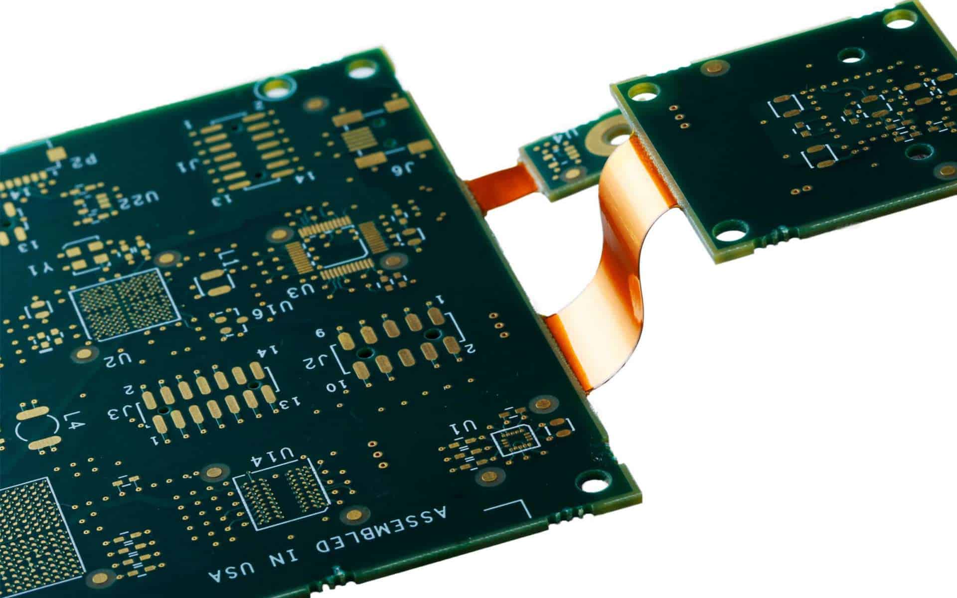
Rigid-flexible printed circuits (rigid FPCs) combine rigid circuit boards and flexible circuits into a single structure. The rigid sections provide mechanical support and component mounting stability, while the flexible sections enable dynamic flexing, bending, or wrapping connections. This makes rigid FPCs ideal for applications where a purely flexible PCB would be too flimsy but a purely rigid board would lack the required flexibility.
Key Properties of Rigid FPCs
- Combines rigid and flexible materials into one circuit
- Rigid areas provide stability for components
- Flexible areas allow dynamic flexing and bending
- Well-suited for complex interconnections
- Can integrate multiple technologies
- Reduces weight and increases product reliability
Applications of Rigid Flexible PCBs
Rigid-flex PCBs are commonly used in:
- Consumer electronics – cell phones, laptops, tablets, wearables
- Automotive electronics – engine control units, infotainment systems
- Medical devices – imaging systems, implants, monitors
- Industrial equipment – robotics, machinery, controls
- Aerospace and defense – avionics, navigation, telemetry
Their ability to integrate rigid and flexible regions makes rigid-flex PCBs ideal for complex and space-constrained electronic packages.
Rigid FPC Design Considerations
Designing a reliable rigid-flex PCB requires careful planning and engineering. Here are some key design factors to consider:
Layer Stackup
The rigid and flexible sections of the PCB can have different layer counts based on circuit needs:
- Rigid sections often have multiple layers for high component density
- Flexible sections may just be single or double layer to minimize thickness
Flex-Rigid Transition
The junction between rigid and flexible areas requires special design:
- Avoid sharp flexing angles – use rounded corners instead
- Minimize rigid-flex thickness mismatches
- Ensure adequate strain relief for flexing
- Test reliability with multiple flexing cycles
Component Placement
Strategic component placement is critical:
- Place high-density components in rigid sections
- Reserve flexible areas just for dynamic interconnections
- Watch component spacing around bends
Material Selection
Compatible materials must be used:
- Rigid sections use standard FR-4 or other rigid PCB materials
- Flexible sections use polyimide or other flexible films
- Adhesive layers join the rigid-flex materials
Fabrication Considerations
Rigid-flex PCB fabrication requires specialized processes:
- Careful alignment during lamination
- Precise rigid-flex edge trimming
- Plated through holes across transition areas
- Controlled depth etching for conductors
Rigid Flex PCB Construction
There are two main approaches to manufacturing rigid-flex PCBs:
Discrete Flex
The rigid and flexible layers are fabricated separately, then joined together in a secondary lamination process.
Pros:
- Simpler process with good control over each section
- Allows different flex/rigid materials to be combined
Cons:
- Additional alignment and lamination steps
- Bonding between layers can be a reliability concern
Integrated Flex
The rigid and flexible materials are laminated together in one process to form an integrated structure.
Pros:
- Simplified manufacturing with no secondary bonding step
- Excellent mechanical reliability at rigid-flex transitions
Cons:
- Limited material selection flexibility
- Lower layer-to-layer alignment precision
| Construction Method | Description | Pros | Cons |
|---|---|---|---|
| Discrete Flex | Rigid and flexible sections fab separately, then bonded | – Simpler process<br>- Material flexibility | – Extra alignment/bonding<br>- Weaker transitions |
| Integrated Flex | Laminated together in one step | – Simplified fabrication<br>- Better transitions | – Limited material options<br>- Lower alignment precision |
Common Rigid Flex Materials
Rigid-flex PCBs combine a variety of rigid and flexible materials engineered for compatibility.
Rigid Substrate Options
- FR-4 – Most common rigid PCB material
- High-Tg FR-4 – Improved thermal and mechanical stability
- Polyimide – An alternative rigid substrate material
- Aluminum or metal core – For high thermal needs
Flexible Substrate Options
- Polyimide films – Kapton, Apical, UPILEX
- LCP films – Riquid 5000 LDS
- Fluoropolymer films – Rogers RO3000 series
Bonding Materials
- Epoxy or acrylic adhesives
- Thermoplastic polyimide films
Proper adhesion between the rigid and flexible materials is crucial for reliability.
Design Rules for Rigid Flex PCBs
Rigid-flex PCBs require following specialized design rules to ensure manufacturability and reliability:
- Minimum bend radius – Avoid sharp bends to prevent conductor cracking and fiber breakage
- Flexible layer thickness – Thinner flex layers allow tighter bending radii
- Conductor width – Compensate for thickness reduction in flexible areas
- Component spacing – Provide adequate clearance around bends
- Plated through holes – Careful design needed at rigid-flex transitions
- Stiffener integration – Manage stresses and support components
Consulting fabrication guidelines is essential for optimizing a rigid-flex design.
Rigid Flex PCB Fabrication Process
Producing a rigid-flex PCB requires a combination of processes drawn from rigid PCB fabrication and flex circuit manufacturing.
Rigid layers – Fabricated like traditional PCBs:
- Imaging, etching, lamination
- Drilling and via metallization
- Surface finishes and soldermask
Flexible layers – Use additive processes:
- Bonding of flex dielectric films
- Printed, etched metal traces
- Selective buildup of layers
Rigid-flex integration – Requires special steps:
- Multi-stage lamination cycles
- Precise trim and etchback of material
- Registration forlayer-to-layer alignment
- Surface finish application on flex areas
The complexity rises with more layers, smaller features, and higher densities.
Rigid Flex PCB Assembly
Assembling components onto rigid-flex PCBs also requires adaptations from standard PCB assembly:
Soldering – Can be challenging on thinner flexible regions:
- Selective heat sinks may be needed
- Reflow profiles must suit flex properties
- Wave soldering usually avoided
Component loading – Needs to account for flexing:
- Adhesives help secure parts on thin flex sections
- Avoid placing heavy parts near bends
- Watch for clearance issues during flexing
Interconnects – Are designed to accommodate movement:
- Wires, cables allow dynamic flex
- Flex PCB jumpers connect rigid sections
Harnesses – Help manage flexing transitions
Testability, rework, and repair are more difficult with rigid-flex circuits.
Rigid Flex PCB Failure Modes
While extremely capable, rigid-flex PCBs are subject to certain failure vulnerabilities that designers should be aware of:
- Flex cracking – Conductor traces can crack with repeated bending stress.
- Delamination – Separation of rigid and flex layers due to flexing or temperature changes.
- Via fractures – Cracks propagating from plated through holes near bend areas.
- Bond defects – Weak adhesion between rigid and flex segments.
- Alignment shifts – Accumulated loss of registration between layers over flexing.
- Warpage – Stresses causing deviations from flatness.
Ensuring adequate bend radii, strain relief, and flex cycle testing helps mitigate these failure risks.
The Future of Rigid Flex Circuits
Rigid-flex PCB adoption will continue expanding as electronics become more compact and complex. Some trends to expect:
- More layers – 12+ layers will become common for added routing flexibility.
- Advanced materials – Lower-loss flex dielectrics and adhesives.
- Tighter features – Continuing shrinkage of traces, spaces, and gaps.
- 3D integration – Rigid-flex combos enabling out-of-plane folding or stacking.
- Embedding – Components and circuits embedded within the rigid-flex layers.
Innovations in rigid-flex PCB materials, design, and manufacturing will open new electronics application spaces.
Frequently Asked Questions About Rigid Flexible PCBs
What are some key advantages of rigid-flex PCBs?
Some of the main benefits of rigid-flex PCBs are:
- Ability to combine rigid stability and flexible dynamics in one circuit
- More compact, space efficient interconnections
- Allows complex 3D routing topologies
- Reduced system wiring and connectors
- Improved reliability compared to cables or wires
- Lower assembly cost compared to discrete PCBs and cables
What are some disadvantages or limitations of rigid-flex PCBs?
Limitations of rigid-flex PCBs include:
- More complex design requirements
- Challenging fabrication processes require expertise
- Potential reliability risks at rigid-flex transitions
- Difficult to repair or rework compared to discrete PCBs
- Limited bend cycle life depends on materials and design
What types of products commonly use rigid-flex PCBs?
Rigid-flex PCBs are found in many applications where complex interconnections are needed in limited space. Typical products include:
- Laptops, tablets, and smartphones
- Automotive electronics and sensors
- Advanced medical equipment and implants
- Aerospace/defense systems and avionics
- Advanced industrial equipment and robotics
How many bend cycles can a rigid-flex PCB withstand?
A rigid-flex PCB’s bend cycle life depends heavily on the materials used and the design. With optimal design, many can withstand thousands to tens of thousands of dynamic flexing cycles. More durable metals and adhesives allow longer lifetimes.
How are components assembled on rigid-flex PCBs?
Component assembly requires adaptions to account for the flexing areas. Soldering can be done with care on thinner regions or avoided entirely. Adhesives help secure parts on flexible sections. Interconnects between rigid areas may use flex circuit jumpers or wiring harnesses.


Leave a Reply