Introduction
Rigid flex printed circuit boards, also known as rigid flex PCBs or flex-rigid PCBs, are a type of printed circuit board that combines rigid and flexible substrate materials. This allows the PCB to have both a rigid section and a flexible section. Rigid flex PCBs provide a number of advantages over traditional rigid PCBs or flexible PCBs alone. Some of the key benefits of rigid flex PCBs are:
- Space and weight savings
- Improved reliability
- Design flexibility
- Cost savings
In this article, we will take a closer look at what rigid flex PCBs are and the key benefits they offer. We will also discuss some of the design considerations when working with rigid flex PCBs.
What are Rigid Flex PCBs?
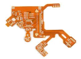
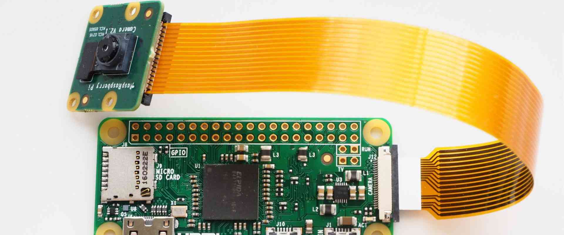
A rigid flex PCB consists of flexible circuitry supported and reinforced by rigid sections or substrates. The rigid sections provide mechanical support while the flexible sections allow dynamic flexing and movement. The rigid and flex sections are laminated together into a single assembly.
The rigid sections are typically made of materials like FR-4, while the flexible sections use polyimide or other flexible polymer substrates. The two materials are bonded together using adhesive films or bonding processes like thermocompression bonding.
Rigid flex PCBs fall into three major categories:
- Rigid-flex: Predominantly rigid with one or more flexible sections
- Flex-rigid: Predominantly flexible with one or more rigid sections
- Balanced rigid-flex: Nearly equal amounts of rigid and flex
The rigid sections provide mechanical stability and ease of component mounting, while the flexible sections allow dynamic movement and three-dimensional routing of traces.
Benefits of Rigid Flex PCBs
Here are some of the major benefits provided by rigid flex PCBs:
Space and Weight Savings
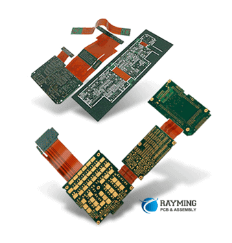
By combining rigid and flexible materials in one PCB, rigid flex designs can conform to unique and complex product shapes. This allows rigid flex PCBs to fold and curve inside products, saving significant space compared to rigid PCBs.
The flexibility also leads to weight savings by eliminating connectors and cable harnesses between PCBs. By routing traces along folded flexible sections, rigid flex PCBs can replace multi-board solutions with a lighter and more compact single board.
Improved Reliability
Rigid flex PCBs can improve reliability in several ways. The folded flexible sections absorb stresses and strains that would otherwise affect solder joints with rigid boards. This reduces solder joint fatigue and failures.
The folded sections also act as “flex friendly” dynamic connectors that accommodate movement and misalignment. This improves resistance to mechanical and thermal stresses.
By reducing connectors and wiring harnesses that are prone to failure, rigid flex PCBs also lower the number of interconnection failure points.
Design Flexibility
Rigid flex PCBs provide much more freedom and flexibility compared to all-rigid boards. Designers can place components on multiple rigid “planes” interconnected by flexible sections. Components don’t have to lie on one flat 2D surface.
Dense or complex circuitry can be distributed across interconnected rigid sections. Critical high-frequency traces can be routed along the flexible sections. Rigid flex PCBs open up solutions not feasible with rigid technology.
| Advantage | Rigid PCB | Rigid Flex PCB |
|---|---|---|
| Component Positioning | Limited to 2D Surface | Components Can be Positioned on Multiple Rigid Planes |
| Routing Channels | Restricted | Added Routing Channels Along Flexible Sections |
| Layer Count | Limited | Higher Effective Layer Count |
Cost Savings
Despite their advanced capabilities, rigid flex PCBs can also lower costs compared to rigid boards in certain situations. By replacing connectors and simplifying interconnects, rigid flex PCBs reduce assembly costs.
Rigid flex PCBs also combine multiple PCBs into a single design. This lowers PCB fabrication, component, and assembly costs compared to multi-board solutions. While rigid flex PCBs themselves have higher fabrication costs per unit area compared to rigid PCBs, their ability to replace multi-board designs can reduce overall system cost.
Rigid Flex PCB Design Considerations
Designing rigid flex PCBs requires attention to details such as:
- Layer stackup: The sequence and materials used for the rigid and flexible layers. Common flex layer materials include polyimide and PEEK.
- Flexible folding areas: Allow sufficient flexible area for the desired degree of folding and prevent overfolding.
- Stiffener placement: Add stiffeners along the fold areas to prevent flexing damage. Stiffeners can be metal, FR-4, or rigid adhesives.
- Component placement: Ensure clearance between components on adjacent rigid sections to prevent collisions during flexing.
- Fabrication: Work with manufacturer to determine special requirements like coverlayers, special adhesives, and handling processes.
Proper guidelines must be followed to prevent mechanical or electrical failures. It is recommended to consultexperienced PCB designers when first designing rigid flex PCBs.
Applications of Rigid Flex PCBs
Rigid flex PCBs are commonly found in the following types of applications:
- Consumer electronics: Cell phones, laptops, cameras
- Automotive: Advanced driver assistance systems (ADAS), infotainment
- Medical: Hearing aids, surgical tools, implants
- Industrial: Robotics, instrumentation, controls
- Military/aerospace: Guidance systems, avionics
Any application with size constraints, dynamic flexing requirements, or complex interconnections can benefit from rigid flex PCBs. The technology provides a unique set of advantages spanning various industries and use cases.
Conclusion
Rigid flex PCBs provide space, weight, reliability, design, and cost advantages compared to traditional rigid boards. By combining rigid and flexible materials, they can conform to complex shapes, fold inside products, enable 3D component placement, absorb stresses, replace connectors, and integrate multiple PCBs. With careful design considerations, rigid flex PCBs enable miniaturization and reliability across many applications. As electronic products continue getting smaller and more complex, rigid flex PCBs will become increasingly important for smart product design and manufacturing.
Frequently Asked Questions
What are the main materials used in rigid flex PCBs?
The rigid sections of rigid flex PCBs typically use standard PCB substrate materials like FR-4 (fiberglass reinforced epoxy). The flexible sections use polyimide or PEEK as the flexible polymer layers. Adhesive films like acrylic or epoxy are used to bond the layers together.
Can components be mounted on both sides of rigid flex PCBs?
Yes, components can be mounted on both sides of the rigid portions of a rigid flex PCB through hole or surface mount technologies. The flexible portions usually only support single sided component mounting.
How many bend cycles can a rigid flex PCB withstand?
The bend life depends on several factors like the flex layer material, bend radius, and any added stiffeners. Typical rigid flex PCBs can withstand hundreds to thousands of dynamic bend cycles if designed properly. More robust designs can endure tens or hundreds of thousands of cycles.
Can rigid flex PCBs be double-sided or multi-layer designs?
Definitely. Rigid portions of rigid flex PCBs can have multiple conductive layers with plated through holes, just like rigid PCBs. The flexible sections are typically limited to 1 or 2 conductive layers.
What are some examples of products that use rigid flex PCBs?
Common examples include mobile phones, laptops, cameras, automotive electronics, medical devices, industrial robotics, aerospace avionics, and many other products that require compact and dynamic circuitry.


Leave a Reply