Introduction to Rigid Flex Circuits
Rigid flex circuits, also known as flex-rigid boards or flex circuits, are a type of printed circuit board (PCB) that consist of rigid and flexible substrates laminated together. The rigid sections provide mechanical support while the flexible sections allow dynamic flexing, bending or wrapping around surfaces.
Rigid flex PCBs provide solutions for electronic devices and products that require:
- Dynamic flexing or movement
- Space/weight savings
- Three-dimensional design
- Vibration dampening
They are commonly used in aerospace, military, medical, consumer electronics and other applications where flexibility, durability and reliability are critical requirements.
Benefits of Rigid Flex Circuits
Here are some of the key benefits that rigid flex PCBs offer:
- Space savings: By combining rigid and flex sections, rigid flex circuits condense electronics into smaller spaces compared to alternatives like cables or connectors between separate rigid boards.
- Flexibility: The flex sections allow bending, folding or wrapping the circuit to fit unique shapes or spaces.
- Reliability: Rigid flex PCBs have fewer interconnections than alternatives, reducing points of failure. The materials and construction also withstand vibration and flexing.
- Lightweight: With smaller size and thinner materials, rigid flex circuits weigh less than using separate rigid boards and cables.
- Design freedom: Rigid flex allows three-dimensional design and packaging of electronics previously not possible with one-sided rigid boards.
Rigid Flex PCB Construction
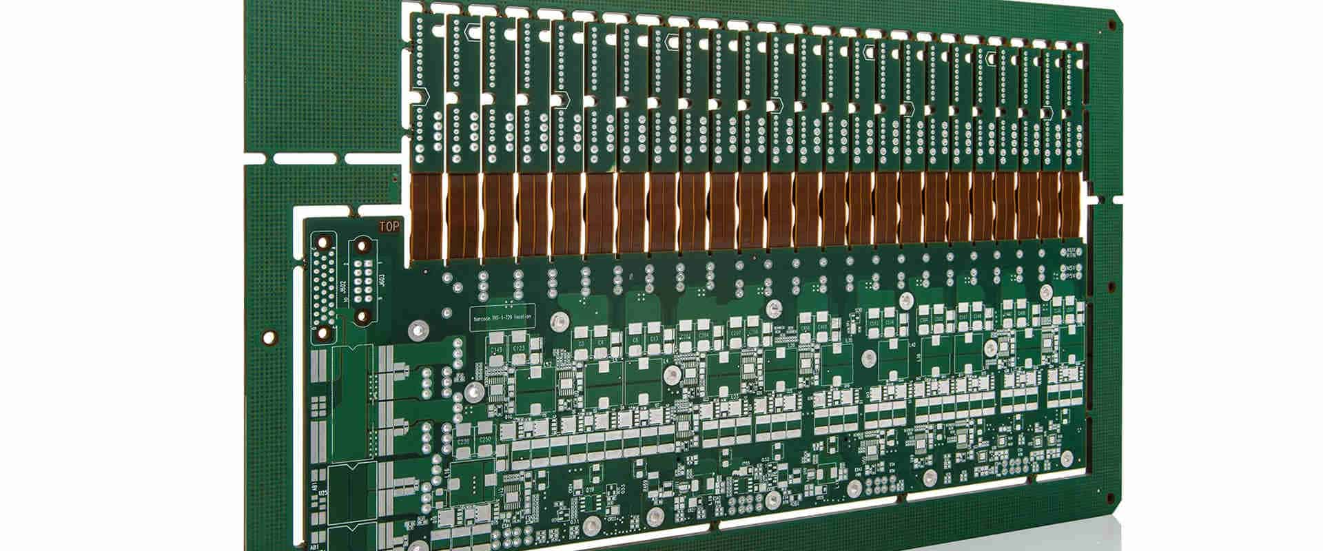
Rigid flex PCBs feature both rigid board material (like FR-4) and flexible dielectric material (like polyimide) laminated together in one circuit board. Here are the basic construction elements:
Rigid layers – Usually FR-4 material. Provide mechanical support and mounting surfaces for components.
Flexible layers – Typically polyimide films such as Kapton. Allow dynamic flexing and bending.
Bonded layers – Adhesive films bond the rigid and flex layers together.
Conductors – Copper traces etched on the rigid and flex sections.
Cover layers – Additional polyimide films bonded on top and bottom for protection.
Stiffeners – Additional rigid sections bonded to flex areas to limit bend radius.
Components – Mounted on rigid portions of the circuit.
Terminations – Connectors or pins attached to board.
This shows two outer flexible layers surrounding an inner rigid layer, with conductive copper traces on the top and bottom. The rigid material provides mechanical support while the thin flexible layers allow dynamic bending and shaping.
More complex rigid flex boards may contain multiple alternating rigid and flexible layers bonded together in a sandwich construction. The designer can tailor the placement of rigid and flex sections to the particular mechanical and electrical needs.
Rigid Flex PCB Design Considerations
Designing a successful rigid flex circuit requires accounting for the unique features and challenging aspects of combining rigid and flexible materials into one functional circuit board.
Here are some of the most important design considerations:
Layer Stackup
The designer must determine the required number of conductive, rigid and flexible layers needed to route traces and contain components. Flex-to-rigid layer ratios and locations are also decided.
Bend Radius
A minimum bend radius must be maintained to prevent failure of conductors. Polyimide flexible layers can bend extremely tight, but conductors can crack if folded too far. Typical minimum bend radius is 10X the board thickness.
Flex Cuts
Flex cuts selectively remove portions of a layer, allowing increased flexibility between sections. Strategic placement and sizing of cuts enables bending and shaping.
Stiffener Placement
Additional rigid stiffener sections are often added to strengthen areas and control bend radius. Stiffener integration must be considered early when planning layer stackup.
Component Placement
Since components can only be mounted on rigid portions, their placement plan must align with planned rigid sections. Large or heavy components may require local stiffening.
Thermal Management
The combination of materials requires special analysis for thermal dissipation. Component heating, rigid/flex thermal isolation, and cooling options must be assessed.
Layout Rules
Special rigid-to-flex clearance rules for traces and pads must be followed to account for shifting during flexing and prevent conductor damage.
Rigid Flex PCB Fabrication Process
Fabricating a rigid flex PCB requires specialized methods to combine rigid board fabrication and flexible circuit manufacturing processes. Here is a general outline of the production workflow:
1. Fabrication Preparation
The fabrication process begins by preparing all of the required materials and processing tools:
- Rigid layers – Cut sheets of FR-4 or other rigid laminate materials.
- Flexible layers – Rolls or sheets of thin polyimide films.
- Bonding films – Adhesives to laminate layers together.
- Base metals – Copper foils for conductors.
- Photoresists – Light-sensitive films.
- Etchants – Chemical solutions.
- Presses – Heated platen presses for lamination.
- Imaging – Tools for imaging resist layers.
2. Circuit Processing
The initial PCB fabrication steps are performed on the individual flex and rigid layers:
- Imaging – Photoresist layers are imaged with circuit patterns using lithography processes.
- Developing – Exposed areas of resist are dissolved, leaving a mask for etching.
- Etching – Unwanted copper is chemically removed to isolate circuit traces.
- Stripping – Remaining resist mask is removed.
This results in finished etched rigid boards and flex circuits before they are combined.
3. Layer Alignment
The rigid and flex layers are precisely aligned in preparation for lamination:
- Cutting – Rigid layers are cut to shape where flex sections will go.
- Alignment – Fiducials and targets are used to align layers.
- Tacking – Layers may be lightly adhered in place prior to lamination.
4. Lamination
The layers are bonded together under heat and pressure:
- Stackup – Layers are stacked in proper sequence with bonding adhesive films.
- Bookending – Stiff plates temporarily bond to top and bottom.
- Pressing – Stack is inserted in heated platen press.
- Curing – Layers fuse as adhesives flow and cure under heat/pressure.
This produces a fully laminated rigid flex circuit board.
5. Final PCB Processing
Post-lamination processing and testing:
- Solder mask – UV-curable solder resist layers are added.
- Finishing – Protective coatings and surface finishes applied.
- Testing – Electrical testing confirms proper functioning.
- Singe/routing – Individual boards are cut from panel.
The finished rigid flex PCBs are now ready for component assembly.
Rigid Flex PCB Design Software
Specialized PCB design software tools are required to handle the unique needs of rigid flex circuits. Here are some typical features:
- Rigid-flex mode – Toggle layers as rigid or flexible
- Teardrop pads – Rounded pad shape at flex-rigid interfaces
- Flex cuts – Removes sections of flex layers
- Bend area outline – Shows minimum bend radius
- Layer smoothing – Smooths layers during flexing
- Impedance tuning – Controls impedance across flex bends
- 3D modeling – Models rigid-flex shape and bending
This functionality allows designers to integrate flexible and rigid requirements into one PCB design. Leading rigid flex design software packages include:
- Altium Designer
- Cadence Allegro
- Mentor Xpedition
- Zuken CR-8000
The right software tools help enable efficient, accurate rigid flex design and avoid potential manufacturability issues.
Types of Flexible Circuits
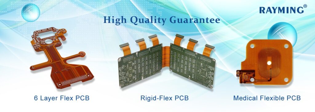
There are a few common variations of flexible PCB construction to suit different design requirements:
Single Sided Flex Circuits
This basic style has conductive traces on only one side of the flex layer. It allows simple dynamic bending in one axis.
Double Sided Flex Circuits
Conductive layers on both sides of the flex core allow more complex routing while still enabling flexing.
Multilayer Flex Circuits
Flex layers can be stacked into multilayer constructions with additional conductive and adhesive layers. This enables dense interconnections.
Sculptured Flex Circuits
Flexible circuits can be folded or formed into 3D shapes. Sculptured flex allows packaging electronics in unique wrapping or contoured applications.
The combination of these flexible circuit variations coupled with rigid sections gives designers extensive possibilities to integrate and package electronics in innovative form factors.
Common Rigid Flex PCB Applications
Here are some examples of products and applications that benefit from using rigid flex circuit boards:
| Application | Use of Rigid Flex PCB |
|---|---|
| Wearable electronics | Dynamic flexing to wrap around limbs and body contours |
| Medical devices | Folding into compact device packaging |
| Mobile phones | Link rigid boards while flexing around hinges and joints |
| Laptops | Interconnect rigid PCBs and integrate flexing hinge |
| Digital cameras | Allow flexibility for compact camera motion |
| Automotive | Withstand vibration while integrating control electronics |
| Aerospace/Military | Rugged flex circuits withstand vibration, thermal stresses |
| Robotics | Enable movement with flexing spine and limb boards |
Any application with requirements for flexibility, three-dimensional packaging and reliability can benefit from the use of rigid flex circuit technology.
Rigid Flex PCB Manufacturers
There are contract manufacturers that specialize in producing rigid flex PCBs using the specialized construction methods required. Here are some of the leading global rigid flex manufacturing partners:
- FlexPCB – One of the first flex circuit companies, founded in 1982 in California.
- Lenthor – Headquartered in Florida, they focus on quick-turn rigid flex manufacturing.
- RayMing – Well-known Taiwanese maker of advanced rigid flex circuits.
- All Flex – Flex circuit manufacturer with operations in the U.S. and China.
- Reid Industrial – UK-based flex manufacturer, also produces flexible heaters and sensors.
- Compass Circuits – Specializes in dynamic flex, multilayer rigid-flex and sculptured flex PCBs.
- Midasco – Provides turnkey flex and rigid-flex engineering and manufacturing.
- Sumitronics – Multinational maker of flex and rigid-flex PCBs for various industries.
- Flexible Circuit Technologies – Leading innovator in dynamic flex applications.
- Minco – Major flex circuit manufacturer for the medical, aerospace, industrial, and electronics industries.
- Mina – Specialized manufacturer of multilayer rigid flex, sculptured flex, and dynamic flex circuits.
Look for potential rigid flex manufacturing partners that have expertise in the specialized processes required to produce this technology. Ensure they can work closely with designers early in the product development process to optimize rigid flex design for both functionality and manufacturability.
Rigid Flex PCB Cost Factors
As a more complex PCB technology, rigid flex circuits tend to have higher costs than common single or double sided rigid boards. Here are some of the factors that influence overall rigid flex PCB pricing:
Layer count – More layers require additional materials, processing, and lamination cycles.
Board size – Larger boards use more base materials.
Flex ratio – More flex area requires additional polyimide films.
Complexity – Intricate rigid-flex interfaces, dense routing, and small features add cost.
Quantity – Economies of scale apply. Lower volumes have higher per-board cost.
Testing – Rigorous inspection and testing adds cost to assure reliability.
Quick-turn – Faster delivery times often command price premiums.
Location – Where circuits are manufactured impacts labor and shipping costs.
Materials – Special materials like polyimide films and adhesives impact cost.
Tolerances – Tighter tolerances require more precision (and cost) to achieve.
Certifications – Some applications require rigorous quality control and documentation.
Always communicate early with potential rigid flex PCB partners to understand cost drivers and receive pricing estimates for a particular design. Cost optimization assistance is also available.
Frequently Asked Questions
Here are some common questions about rigid flex PCB technology and fabrication:
What are typical minimum bend radiuses for flex circuits?
The minimum bend radius is approximately 10 times the total board thickness. So a rigid flex PCB with a total thickness of 0.050″ would have a minimum bend radius of 0.5″.
Are via holes allowed in the flex area?
It is recommended to avoid vias in the dynamic flex region as these rigid holes can impact bending and reliability. Blind/buried vias and other connection methods are preferred.
What line width/spacing rules apply for rigid-to-flex areas?
Special clearance rules usually apply between traces crossing rigid-flex boundaries to allow for shifting during bending. A typical rule is minimum 5 mil line/space in this transition area.
Can components be mounted directly on the flex portion?
Generally it is advised to mount components only on rigid sections, as their mass can impact flexing. But some simple, lightweight surface-mount devices may be allowable.
How many flex bending cycles are typical rigid flex circuits rated for?
Properly designed rigid flex PCBs often achieve 500,000+ dynamic flex bending cycles before failure of conductors can occur. The design, materials, and bend radius impact cycle life.
Conclusion
Rigid flex PCB technology enables unique solutions for electronics integration and interconnect previously not possible with rigid boards alone. By combining rigid and flexible materials into one circuit, rigid flex accommodates dynamic shaping and motion along with dense component mounting.
With the proper design expertise, materials selection, and manufacturing methods, rigid flex PCBs deliver the enhanced functionality, compact form factors, and reliability needed in cutting edge industrial, aerospace, medical and consumer applications. As electronic devices continue requiring increased flexibility and durability, adoption of rigid flex circuit boards is expected to grow for enabling the electronics integration challenges of the future.


Leave a Reply