
Introduction
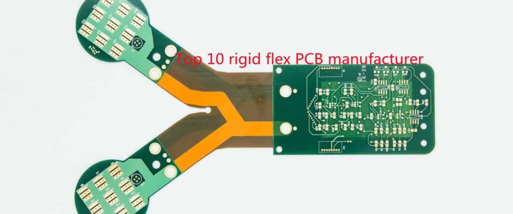
Rigid-flex PCBs combine rigid and flexible circuitry into a single structure, providing solutions for complex interconnect and packaging requirements. They allow three-dimensional configuration and dynamic flexing to optimize electrical performance and interconnect solutions not practical or possible with rigid boards alone.
However, rigid-flex PCBs have unique design and manufacturing requirements that must be considered to achieve a robust, reliable product. This article provides key design guidelines and considerations for rigid-flex PCBs.
Materials Selection
Choosing the right materials is critical for rigid-flex performance and reliability.
Rigid Portions
The rigid portions of the PCB typically use standard FR-4 or high Tg FR-4 laminates. These provide adequate stiffness and facilitate processing and assembly similarly to a normal rigid PCB.
Flexible Portions
The flexible layers use polyimide materials like Kapton or Upilex. These withstand repeated flexing without cracking or degrading electrical performance. Typical flex laminate thickness is 2-4 mils. Thinner laminates allow tighter bend radii but are more prone to handling damage.
Bonding Films
Acrylic or thermoplastic polyimide adhesive films bond the rigid and flex layers together. They withstand thermal excursions during lamination while providing high shear and peel strength at the interfaces. Flexible acrylic adhesives can better accommodate mismatches in coefficient of thermal expansion between rigid and flex layers.
Coverlayers
Additional polyimide cover layers may be laminated to the top and bottom of the flex circuitry to increase dielectric isolation and provide environmental protection. 1-2 mil coverlayers are typical.
TABLE: Common Rigid-Flex Materials
| Material | Description |
|---|---|
| FR-4 | Standard rigid PCB laminate |
| High Tg FR-4 | Improved thermal and mechanical performance |
| Polyimide | Flexible dielectric layers (Kapton, Upilex, others) |
| Bonding films | Acrylic or polyimide adhesive films |
| Coverlayer | Thin polyimide layer for protection |
Layer Stackup
The layer stackup defines the sequence of dielectric, copper, and adhesive layers in the PCB. Careful stackup design is required to optimize electrical performance and manufacturability.
- Place at least two layers of copper on each side of the polyimide flex layers to prevent curling and facilitate handling and processing.
- Use thicker 2 oz or 3 oz copper to withstand flexing stresses and avoid cracking.
- Symmetrically arrange flex layers between rigid layers to avoid bending stresses.
- Minimize the number of different laminate materials used.
- Allow sufficient adhesive bleed-out distance from flex layers to avoid wetting onto rigid areas.
Bend Radii
The bend radius is one of the most critical design parameters for rigid-flex PCBs. Tight bend radii allow compact 3D configurations but increase stresses on the flex layers.
Minimum Bend Radius
The minimum bend radius depends on:
- Flex laminate material and thickness
- Number of flexible layers
- Copper thickness
- Presence of coverlayers
Typical minimum bend radii range from 3-10X the total flex layer thickness. Polyimide properties decline significantly below 3X thickness.
bend radius
Inside Bends
Use maximum achievable radii for inside bends which experience the highest stresses.
Outside bends
Can utilize the minimum bend radius.
Dynamic Flexing
Apply more conservative bend radii for dynamic or repeated flexing to avoid accumulated damage over time. Up to 10X total thickness.
bend radius TABLE
| Flex Layer Thickness | Minimum Bend Radius |
|---|---|
| 2 mil | 6-8 mil |
| 3 mil | 9-12 mil |
| 4 mil | 12-16 mil |
Routing Rigid-Flex Boards
Unique considerations apply when routing rigid-flex PCBs:
- Avoid routing across the flex-rigid interface which can compromise laminate adhesion. Route up to but not across.
- Provide tear-stop vias at the intersections between rigid and flex sections to prevent propagating cracks.
- Route flex layers before rigid layers. Flex layers have tighter routing tolerances.
- Maintain wider trace widths and spacing on flex layers. Use minimum 8-10 mil lines and spaces.
- Allow for additional trim distances between circuits and board edge. Flex portions may shift during lamination.
Component Placement
Optimize component placement across rigid and flex areas:
- Place sensitive analog or high-speed components on rigid sections to minimize noise and maintain controlled impedances.
- Reserve flexible sections for interconnections only with no active components.
- Avoid placing heavy components on thin flexible areas. This can cause excessive sagging.
- Orient components to avoid tombstoning during reflow process. Adhesives and uneven heating of rigid-flex boards can cause issues.
- Rotate rectangular components by 45 degrees to reduce stresses on solder joints from dynamic flexing.
Via Transitions
Carefully design transitions between component pads on rigid sections and trace vias in flexible areas:
- Use teardrop shapes on all pad corners to avoid acute angles which concentrate stresses.
- Place annular ring pads for vias in flex sections to maximize solder joint strength. Avoid direct connections.
- Increase pad sizes where traces transition from rigid to flex for increased strength.
Board Stiffeners
Adding stiffeners between or around flexible sections provides several benefits:
- Limits out of plane bending which can fracture copper traces.
- Allows use of smaller bend radii.
- Facilitates handling and assembly without damage.
- Can positively locate specific bends.
Common stiffening options:
- Upturn mounting tabs on perimeter of board
- Place rectangular rigid portions between flex areas
- Use adhesive dots, polyimide strips, or additional coverlayers
Electrical Considerations
Several factors unique to rigid-flex require special attention for electrical performance:
Layer Transitions
The stackup changes between rigid and flex sections can alter impedance values and introduce reflections. Careful modeling is required to match impedances.
Thermal Stresses
Can cause small dimensional changes in trace spacing and dielectric thickness, altering impedance.
Bend Stresses
Will also change spacing and thickness parameters. Most pronounced on inner bend layers.
Signal Routing
Route critical signals along continuous rigid sections only, not across bends. Use flex only for non-critical signals and connections.
Shielding
May be required between rigid and flex or adjacent flex layers due to reduced isolation.
Testing and Inspection
Thorough testing and inspection is recommended for finished rigid-flex boards:
Visual Inspection
Inspect via transitions, component areas, bends, and stiffeners for potential defects using a microscope where required.
Dimensional Checks
Verify minimum electrical spacing, conductor widths, hole sizes, and registration using optical comparators.
Netlist Testing
Perform in-circuit testing after assembly to verify proper connections on both rigid and flex layers.
Continuity Testing
Use flying probe or bed-of-nails to check for cracks or opens in flex conductor layers.
Cross-section Analysis
Destructive cross-sectioning should be used during qualification to verify proper layer alignment, resin curing, and bond integrity.
FQA
Q: What are some key advantages of rigid-flex PCBs?
A: Rigid-flex PCBs provide solutions for complex 3D configurations, space constraints, and dynamic flexing requirements not achievable with rigid PCBs alone. They optimize electrical performance by locating signals and components on rigid sections. Rigid-flex is ideal for products requiring compacts size and complex motion or interconnections.
Q: What are some typical applications for rigid-flex PCBs?
A: Common applications include folding handheld electronics, wearables, cables, disk drives, packaging interconnects, automotive cameras, and medical electronics. The compact 3D packaging and dynamic flexing abilities address constraints in these products.
Q: What special considerations apply to soldering rigid-flex PCB assemblies?
A: The uneven heating of mixed material types can lead to issues with solder reflow. Using a thermal profiling oven provides tighter control over the reflow process. Preheating before reflow also helps minimize thermal gradients. Adhesives may also be used to temporarily bond components prior to reflow.
Q: How are components assembled onto rigid-flex PCBs?
A: Both surface mount and through-hole components can be assembled onto rigid-flex boards, using standard pick and place and wave soldering or reflow equipment. Some additional fixtures or hand-loading may be required to prevent damage to flexible areas during assembly.
Q: What testing should be performed on prototype rigid-flex designs?
A: Prototyping should include thorough inspection of flex areas under maximum bending, environmental testing to identify potential cracks or failures, and shock/vibration testing to verify all components are adequately supported. Electrical testing before, during, and after mechanical stresses can identify intermittent opens or changes in performance.


Leave a Reply