Introduction to Rigid Flex PCBs
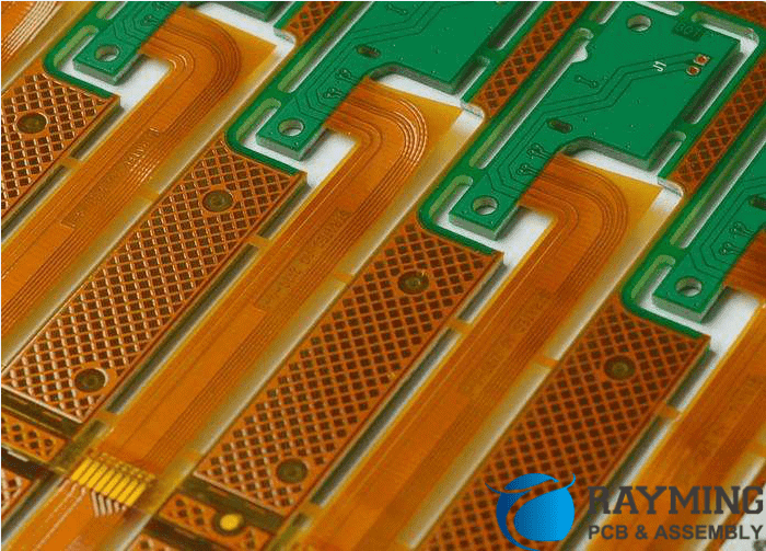
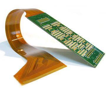
A rigid-flex printed circuit board (PCB) combines rigid and flexible substrates to create a circuit board that can bend and flex. Rigid-flex PCBs provide solutions for complex interconnect and space/weight requirements that cannot be achieved with rigid PCBs alone.
Some key benefits of rigid-flex PCBs:
- Compact design: Rigid-flex PCBs can fold and bend to fit into tight spaces. This allows for smaller and lighter end products.
- Flexibility: Literally! The flex sections allow the PCB to bend and move dynamically. This enables new packaging solutions.
- Reliability: The circuits are lithographically printed, providing reliable connections. The flex areas absorb stresses from motion or vibration.
- Weight savings: By eliminating wires and connectors, rigid-flex PCBs weigh less than rigid PCB assemblies.
- Layer stackup flexibility: Rigid sections can have thicker layer stackups with more layers than the thinner flexible sections.
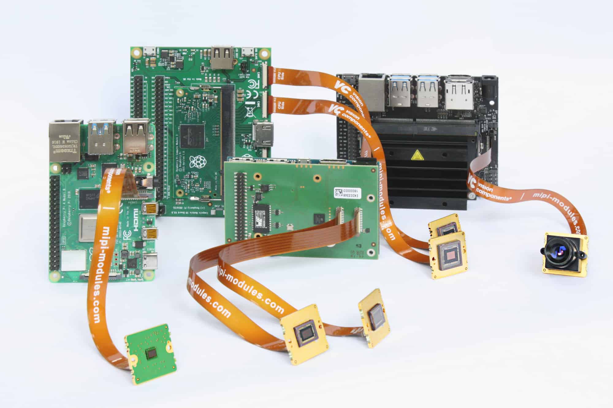
Rigid-flex is ideal for applications such as cameras, laptops, mobile phones, printers, medical devices, and aerospace electronics. The rigid sections provide structural support while the flex areas connect multiple rigid boards.
Rigid-Flex Design Considerations
Designing a rigid-flex PCB requires special considerations:
- Materials: Thermal expansion differences between rigid and flex materials can cause reliability issues. Careful material selection is critical.
- Flex to rigid transitions: The number of layers changes at these intersections. Special stackup and layout techniques avoid problems.
- Dynamic flexing: Avoid sharp bends. Manage stresses on traces to prevent cracks. Allow room for motion.
- Layout: Parts must be secured to rigid sections. Plan for assembly. Ensure trace lengths support high-speed signals.
- Fabrication: Work closely with your PCB manufacturer during design. Not all shops can handle rigid-flex boards.
Careful planning is needed to account for the mechanical, electrical, and manufacturing aspects unique to rigid-flex PCBs.
Creating Rigid-Flex PCBs in Altium
Altium Designer provides specialized tools to help you design rigid-flex PCBs. Here is an overview of the process:
1. Define Rigid-Flex Stackup
After setting your board outline and footprint placement, define the layer stackup. Add flex layer spans where the board will bend. Ensure contiguous layer numbering between rigid and flex sections.
[Insert image of rigid-flex stackup definition]
2. Create Mechanical Contours
contours PCB editor to designate rigid and flex areas. This defines the mechanical layer shape.
[Insert image showing rigid/flex contours]
3. Assign Materials
Apply suitable rigid and flex materials to each contoured section. This is vital for analysis.
4. Manage Layer Transitions
At layer transitions, use planes and polygonal pour features to avoid being shorted. Diagonal corners help prevent cracks.
5. Add Flex Bends
In the PCB editor, add bends showing where the board will flex during use. Define the bend radius and gap.
6. Perform Analysis
Use rigid-flex rules checks and 3D modeling to verify the design. Thermal analysis is also critical.
7. Generate Documentation
Output layer stackup drawings, assembly files, and fabrication documentation for manufacturing.
With the right design approach, Altium provides all the necessary tools to create a successful rigid-flex PCB project. Work closely with your fabricator to ensure manufacturability.
Pros and Cons of Using Altium for Rigid Flex PCBs
| Pros | Cons |
|---|---|
| Dedicated rigid-flex design environment | Steeper learning curve than standard PCB design |
| Flex/rigid layer contours and materials | Must define complex layer stackups and transitions |
| Smooth layer transitions at intersections | Advanced analyses require additional configuration |
| 3D modeling of flexed/unflexed states | More back-and-forth with manufacturer typical |
| Documentation output tailored for rigid-flex | Shorter track record than traditional PCB workflows |
Applications and Examples of Rigid Flex PCBs
Here are some examples of how rigid-flex PCBs are used in various products:
Consumer Electronics
- Cell phones: Connect display/keyboard to main PCB
- Laptops: Interconnect motherboard and display
- Digital cameras: Link lens to control PCBs
Medical Products
- Hearing aids: Fold to fit in ear canal
- Wearable monitors: Flex with body movement
- Implants: Withstand repeated flexion
Industrial
- Printers: Route signals from control board to printhead
- Robotics: Flex with moving joints
- Avionics: Withstand vibration/harsh environment
Transportation
- Automotive cameras: Reliable despite shock/temp
- Hybrid/electric vehicles: Lightweight interconnects
Aerospace
- UAVs: Fold wings and link avionics
- Satellites: Flex solar arrays and antennae
The compact design and dynamic flex capability make rigid-flex PCBs ideal for advanced products across many industries.
FQA
What is the minimum bend radius for flex PCBs?
The minimum bend radius depends on the thickness and composition of the flexible material. As a general guideline, a minimum bend radius of at least 10 times the flex thickness is recommended. For example, for a 50μm thick flex, the minimum bend radius would be 0.5mm.
Can components be mounted directly on the flex section?
It is generally not recommended to mount components directly on the flex area of a rigid-flex PCB. The flexing can damage solder joints and cause components to detach. Components should be mounted to rigid sections only.
What are some best practices for routing traces in the flex area?
Use 45°angled traces at layer transitions, avoid 90° bends, minimize trace length in dynamic areas, avoid vias in flex, match trace widths to layer transitions, and provide strain relief cutouts.
How many times can a rigid-flex PCB be flexed before failure?
Lifecycle testing is used to determine the flex life rating. This depends on the materials, stackup, geometry, and amplitude of flexing. Most rigid-flex designs can withstand hundreds of thousands to millions of dynamic flex cycles before failure.
What type of connectors work well for rigid-flex PCBs?
FFC/FPC connectors allow a rigid-flex board to plug into another PCB. Flexible ribbon cables can also connect rigid-flex boards. Board-to-board connectors like mezzanine connectors provide a robust option too.


Leave a Reply