Introduction
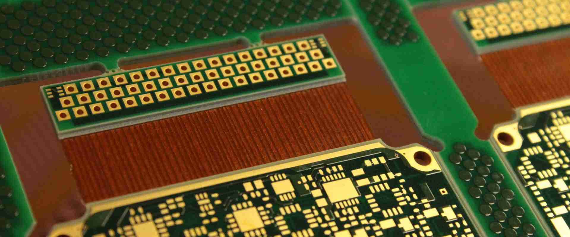
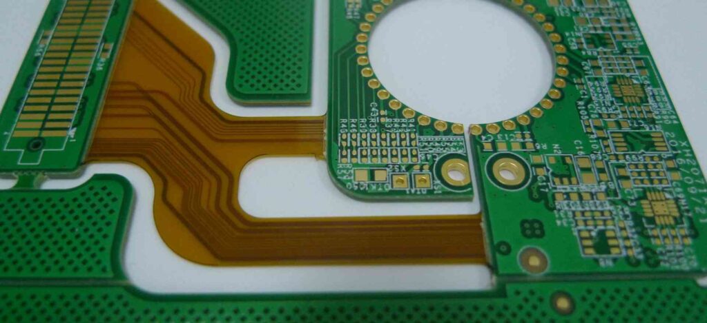
Rigid-flex PCBs, also known as rigid-flexible printed circuit boards, are a hybrid of rigid PCBs and flexible PCBs. As the name suggests, rigid-flex PCBs provide both stiffness and flexibility in the same board. This enables them to take on complex 3D shapes and bend around objects, while still providing rigid mounting surfaces for electronic components.
Rigid-flex PCBs open up new possibilities in product design and miniaturization that are not possible with rigid PCBs alone. They allow electronic circuits to fit into tight, curved spaces in products like cell phones, wearables, medical devices, aerospace avionics and more.
In this comprehensive guide, we will cover:
- The benefits and applications of rigid flex PCBs
- Rigid-flex materials and construction
- Considerations for designing and laying out rigid-flex PCBs
- Manufacturing processes
- Quality control and testing
- Cost factors
- Major rigid-flex PCB manufacturers
Understanding these key aspects of rigid flex technology will help you determine if it is suitable for your next product design and how to approach prototyping and manufacturing.
Benefits and Applications of Rigid Flex PCBs
Here are some of the main benefits that rigid-flex PCBs offer:
- Conforms to different shapes: Can fold and bend to fit curved surfaces and moving parts
- Miniaturization: Enables smaller and more compact product designs
- Flexibility: Dynamic flexing withstands vibration, shock and motion
- Reliability: Eliminates interconnections between separate rigid PCBs
- Weight reduction: Weighs less than using multiple rigid PCBs
Some of the major applications that utilize rigid-flex PCBs include:
Consumer Electronics
- Cell phones
- Laptops and tablets
- Digital cameras
- Wearable devices
- Drones
Medical Devices
- Hearing aids
- Pacemakers
- Blood glucose monitors
- Ultrasound probes
- Endoscopes
Industrial
- Robotics
- Automotive electronics
- Avionics and military systems
- Missile guidance systems
Telecommunications
- Servers
- Data centers
- Networking hardware
Rigid-Flex Materials and Construction
There are several material considerations when designing and constructing a rigid-flex PCB:
Dielectric Layers
The dielectric layers provide insulation between the conductive traces and act as the base material for the entire board. Some common rigid-flex dielectrics include:
- Polyimide (PI): Used for the flexible sections. High temp resistance.
- FR-4: Glass reinforced epoxy. Used for the rigid sections.
- PTFE: Poly Tetra Fluoro Ethylene. Has excellent chemical resistance.
- Polyamide: Cost effective option.
Copper Layers
The copper layers are etched to form the conductive traces, ground planes, etc. Some constructions use thicker copper on the rigid sections for better heat dissipation and thinner copper on the flex areas.
Coverlay/Masking
The coverlay or solder mask layer helps insulate the copper traces and prevent solder bridges. Polyimide film is often used over the flexible areas.
Stiffeners
Optional rigid stiffeners made from aluminum or FR-4 can be added to strengthen the board.
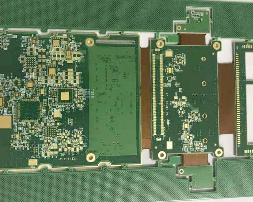
Here are some common rigid-flex layer stackups:
| Construction | Layer Stackup |
|---|---|
| 4 Layer | Rigid PCB / Flex PCB / Rigid PCB |
| 6 Layer | Rigid PCB / Flex PCB / Rigid PCB / Flex PCB / Rigid PCB |
| 8 Layer | Rigid PCB / Flex PCB / Rigid PCB / Flex PCB / Rigid PCB / Flex PCB / Rigid PCB |
The number of layers can also be mixed, such as a 6 layer rigid section connected by a 2 layer flex section.
Design and Layout Considerations
Careful design and layout is critical to ensure the rigid-flex PCB bends properly and avoids damage. Here are some key guidelines:
Flexible and Rigid Areas
- Clearly define the sections that must remain rigid and the sections that require dynamic flexing.
Component Placement
- Place components only on rigid sections, not on the flexing areas.
- Distribute components to avoid uneven stress during flexing.
Trace Routing
- Use teardrop pads where traces connect to vias.
- Avoid traces perpendicular to the bend axis.
- Use curved traces instead of 90° traces.
- Minimize trace length changes between layers.
Bend Radius
- Maintain the minimum bend radius specified for the flex material.
- Consider both static and dynamic bend radii.
- Increase bend radius to improve flex life.
Stiffeners
- Strategically place stiffeners to prevent unwanted flexing.
- Allow sufficient clearance around stiffeners for flexing.
Vias
- Avoid vias in dynamic flex areas.
- Fill vias to prevent solder wicking into the holes.
Tolerances
- Account for shrinkage of flexible circuits.
- Tighten tolerances on outline and cutouts.
Testing
- Build prototypes for bend testing.
- Use finite element analysis to model stresses.
Following these guidelines will help avoid cracking, delamination, open traces, and other defects during bending. Work closely with your PCB manufacturer during design review.
Manufacturing Processes
Producing a rigid-flex PCB requires specialized fabrication. Here are some of the key manufacturing processes:
Laminating
- Layers of rigid and flex materials are laminated using adhesive films and high heat and pressure.
- Precise alignment and lamination pressures are critical.
Drilling
- Excellent hole wall quality and precision is required, especially at layer transitions.
- Plated through holes (PTHs) interconnect between rigid and flex layers.
Etching
- Etching to form conductors requires tight process controls.
- Can use different trace densities on rigid and flex layers.
Coverlay and Solder Mask
- Liquid photoimageable (LPI) masks enable solder mask openings at the bend areas.
- Discontinuities in the mask at layer transitions require special attention.
Component Assembly
- SMT and through-hole assembly only on rigid areas.
- May use glue dots to “lock” components in place.
Final Shaping
- Carefully cutting and scoring to profile edges.
- Visual checks that conductors extend properly to edges.
Testing and Inspection
- Electrical testing
- Automated optical inspection (AOI)
- X-ray inspection of BGAs and vias
- Cross-sectioning
- Flex and bend testing
Throughout the fabrication process, any misalignment, warp, thin spots, or wrinkles can cause reliability issues. Rigid-flex PCBs require advanced manufacturing expertise.
Quality Control and Testing
Verifying the quality and reliability of rigid-flex PCBs requires thorough inspection, testing and analysis:
- Dimensional Inspection: Confirm trace spacing, hole sizes, pad sizes, etc. are within specified tolerances.
- Electrical Testing: Test for opens, shorts, and proper board functionality after assembly.
- Automated Optical Inspection (AOI): Scan boards to check component placement, solder joints, etc.
- X-Ray Inspection: Verify internal layer alignment and PTH quality.
- Cross-Sectioning: Cut cross-sections to inspect plated through holes, layer to layer alignment, and more under a microscope.
- Solderability Testing: Verify the wetting action, contact angle and surface finishes of solder pads.
- Bend Cycle Testing: Flex boards through repeated bend cycles and inspect for cracks, delamination and electrical failures.
- Environmental Stress Testing: Expose boards to extreme temperatures, humidity, vibration, etc. per application needs.
- Shear and Pull Testing: Measure the strength of plated through holes and solder joints when stressed.
- Post-Assembly Functional Testing: Validate complete board operation through electrical or mechanical functional tests.
The combination of inspections, tests, checks, and safeguarding at each fabrication step ensures the reliability and performance of the completed rigid-flex assembly.
Cost Factors
Here are some of the key factors that affect the costs of rigid-flex PCBs:
Layer Count: Additional layers increase material costs. High layer counts also lower yields.
Board Size: Larger boards use more base materials. Smaller boards improve panel utilization.
Flex Length: Longer flex sections require more specialized polyimide material.
Design Complexity: High component densities, small features, and tighter tolerances require more effort.
Testing and Inspection: Extensive quality validation at each step adds cost.
Volume: Higher volumes improve cost efficiency through better utilization of manufacturing tools.
Location: Labor, facilities, and logistics costs vary by geographic location.
In general, rigid-flex PCBs fall into the category of advanced PCB technologies which command higher costs due to the materials and manufacturing processes involved. However, they enable unique product designs that offset the PCB cost with substantial benefits.
Major Rigid Flex PCB Manufacturers
Some of the leading global providers of rigid-flex PCB fabrication and assembly services include:
- TTM Technologies
- AT&S
- Compeq
- Ibiden
- SEMCO
- Tripod Technology
- Flexium Interconnect
- Multi-Fineline Electronix (MFLEX)
- Streamline Circuits
- All Flex
Most are located strategically in major electronics manufacturing hubs around the world, such as in the United States, China, Taiwan, Japan, and Korea. When selecting a manufacturing partner, look for expertise specific to rigid-flex PCBs as the processes and quality controls required differ significantly from standard rigid PCB fabrication.
Conclusion
Rigid-flex PCB technology enables solutions not realizable with rigid printed circuit boards alone. With both stiff and dynamic flexing ability combined in one printed circuit board, rigid-flex opens new possibilities for miniaturized and conformal product designs.
However, specialized materials, design expertise, and advanced manufacturing processes are required to produce functional and reliable rigid-flex PCBs. Working closely with a knowledgeable industry partner experienced in rigid-flex fabrication is key to successfully utilizing this technology in a new product.
The unique benefits rigid-flex PCBs offer continue to drive adoption in fields such as consumer electronics, medical devices, industrial equipment, aerospace, and others. As products demand further miniaturization and integration, rigid-flex PCBs will remain an enabling technology for many applications.
FQA
What are the main advantages of rigid flex PCBs?
Some of the key advantages of rigid-flex PCBs are the ability to:
- Conform to different shapes and bend around objects
- Enable smaller, lighter and more compact product designs
- Withstand vibration, repeated flexing, and motion
- Eliminate connectors between separate rigid PCBs
- Improve reliability compared to using connectors
What are some examples of products that use rigid flex PCBs?
Rigid-flex PCBs are used in many products including:
- Laptops, cell phones, tablets, wearables
- Medical devices like hearing aids, pacemakers, blood analyzers
- Drones, robotics, aerospace avionics
- Automotive electronics and instrumentation
What special considerations are needed when designing rigid flex PCBs?
Key rigid-flex design considerations include:
- Defining rigid and flexible sections
- Component placement only on rigid areas
- Routing traces to avoid splits and 90° angles
- Maintaining minimum bend radius
- Using teardrop vias and filled vias
- Tightening tolerances on outlines and cutouts
Why are rigid flex PCBs more expensive than rigid PCBs?
Rigid-flex PCBs cost more due to:
- Specialized materials like polyimide flex dielectrics
- More complex fabrication process steps
- Tighter tolerances and process controls
- Lower manufacturing yields
- Extensive testing and inspection
What are some leading manufacturers of rigid flex PCBs?
Some of the major rigid-flex PCB manufacturers include:
- TTM Technologies
- AT&S (Austria)
- Ibiden (Japan)
- Compeq (Taiwan)
- SEMCO (Korea)
- Tripod Technology (Taiwan)
- Multi-Fineline Electronix (MFLEX)


Leave a Reply