Introduction
Rigid flex circuits, also known as rigid flexible circuits or flex-rigid circuits, are a type of printed circuit board that combines rigid and flexible substrate materials to create lightweight and durable electronic interconnect solutions. As the name suggests, rigid flex circuits provide the benefits of both rigid boards and flexible circuits in a single design.
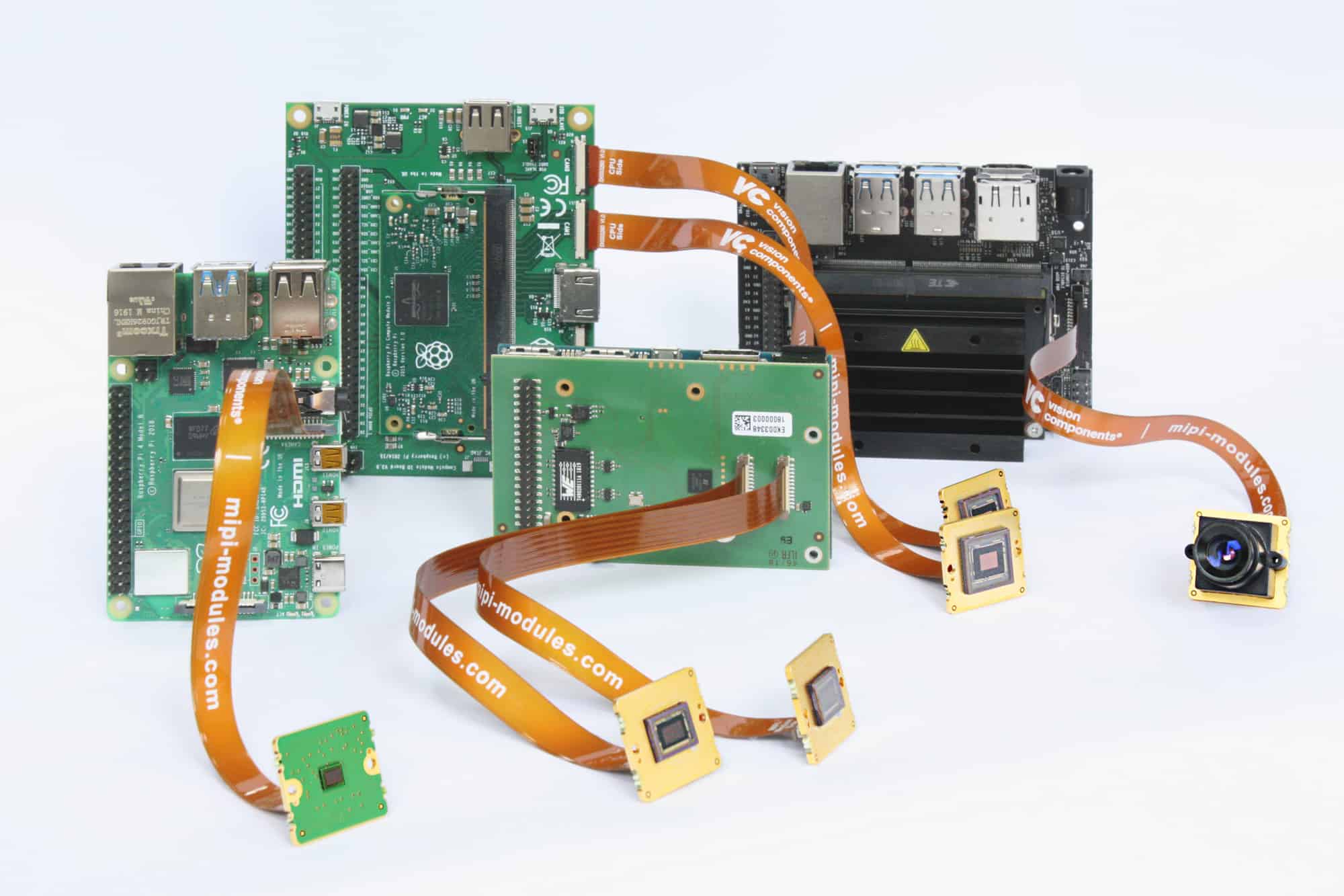
In rigid flex circuits, the rigid sections provide mechanical support and ease of component assembly, while the flexible sections allow dynamic flexing, folding, and wrapping around objects. This makes rigid flex circuits ideal for manufacturing compact, portable electronic devices with moving parts or unconventional form factors. From mobile phones and laptops to wearable devices, automotive electronics, and medical equipment, rigid flex circuits are found in a vast range of applications today.
This article provides an overview of rigid flex circuit technology, design considerations, manufacturing processes, and applications.
What is Rigid Flex Circuitry?
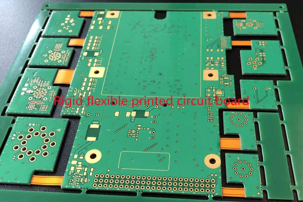
A rigid flex circuit consists of flexible circuit materials laminated onto rigid circuit board substrates. The rigid sections are typically made of FR-4 or polyimide, while the flexible sections use polyimide or polyester films. Conductive traces are etched on both sides of the substrate to interconnect electronic components. The rigid and flex sections are then laminated together using adhesive films.
Rigid flex circuits provide the combined benefits of:
- Rigid circuit boards – mechanical strength, ease of assembly and component mounting, good thermal performance
- Flexible circuits – dynamic movement, compact and lightweight form factor, high resistance to vibrations
This makes rigid flex circuits suitable for:
- Applications with complex motion or folding requirements
- Irregular or curved product enclosures and surfaces
- Devices where weight and space are constrained
- High stress environments with shock/vibration concerns
Some key properties and advantages of rigid flex circuits include:
- Combines rigid and flexible circuits into one interconnect solution
- Enables 3D circuit stacking and shaping
- Withstands vibration, shock, and repeated flexing
- Ideal for high density interconnections
- Allows miniaturization and weight reduction
- Reduces connectors and cables through integration
- Low risk of failure at connection interfaces
- Facilitates automated assembly and production
Construction and Materials
Rigid flex circuits can have single, double, or multilayer circuitry on the rigid sections. Flexible sections usually only have single or double layer trace routing.
Rigid layers are typically made of:
- FR-4 glass epoxy
- Alumina
- Polyimide
- Carbon fiber reinforced materials
- Ceramics
Flexible layers commonly use:
- Polyimide films
- Polyester films like PET
- PEN films
Adhesive films bond the rigid and flex layers together. Coverlays and solder masks may be applied to protect conductive traces. Rigid sections have higher thickness than flexible parts. Components are mounted on the rigid portions only.
Design Considerations
Designing an effective rigid flex circuit requires careful planning and engineering analysis. Here are some important design considerations:
Layer Stackup
Determining the layer stackup is an early stage design decision which impacts flexibility, trace routing, thermal performance, and manufacturability. A cross-section of the layer stackup must be defined.
Typical stackups have outer flexible layers laminated to inner rigid layers. Rigid sections often contain multiple conductive layers separated by dielectric, while flex sections have one or two trace layers. High layer counts allow increased circuit density but reduce flexibility.
Rigid-Flex Transition
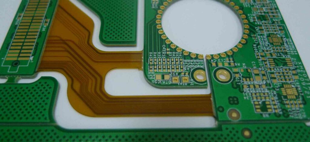
The junction between rigid and flexible materials is a critical aspect of rigid flex circuits. Sharp transitions can cause mechanical stresses and trace cracking. The rigid-flex junction should have a gradual curve to avoid sharp angles.
Annular ring or direct laminate fabrication can produce smooth transitions. Minimum bend radii must be followed to prevent conductor damage.
Bend and Fold Geometry
The bending and folding requirements dictate the rigid-flex layout. Simple folds in one axis are easiest to implement, but multi-axis folding is also possible.
Dynamic folds should avoid creasing directly on traces. Allow sufficient spacing around inside/outside fold curves. Use larger bend radii and consider distributed folds for high-cycle applications.
Electrical Interface
Transmission lines routing from rigid to flex sections can reflect signals at impedance mismatches. Controlled impedance traces and matching impedances on both sections reduce discontinuities.
Vias, pins, or connectors may be used to transition between layers. Strategies like backdrilling or staggered vias can control stub effects. Flex-to-rigid connectors allow detachability.
Thermal Management
The thermal characteristics differ between rigid and flexible materials. Heat sinks, thermal vias, and copper fills help dissipate heat from components on rigid areas. Careful placement avoids hotspots in flex regions.
High layer count rigid sections have better thermal performance than thin flex layers. Adding metal stiffeners or heat spreaders improves heat transfer.
Component Layout
Electronic components and connectors should be positioned only on rigid portions, avoiding flexing areas. Critical components are placed near board centers or supported sections.
A rigid “island” can be used to mount components surrounded by flexible panels. Components should be oriented to avoid stresses from folding or vibration.
Manufacturing Considerations
Designs must account for rigid flex manufacturing processes and constraints. Simpler layer stackups, minimal layer transitions, and larger features aid manufacturing yield.
Panel utilization, fixturing, registration, and handling during assembly should be considered. Test points should be accessible after assembly.
Fabrication and Assembly
Rigid flex circuits require specialized fabrication. Here are some key processes:
Lamination
Layers of rigid and flexible materials are arranged in a stackup and laminated under heat and pressure. Adhesive films bond the layers together. Registration is critical to align layers.
Etching
Conductive copper traces are formed by removing unwanted metal from laminate sheets through etching. Photolithographic processes transfer the circuit patterns.
Hole Formation
Holes are drilled or punched through the board to create vias for trace interconnection between layers. Flexible sections require special micro-drilling.
Coverlay and Solder Mask
Coverlay films or liquid solder masks are added to protect traces from environmental exposure and prevent shorting. Openings are created for soldering.
Stiffener Integration
Metal stiffeners may be embedded in the stackup or attached externally to stiffen specific rigid areas and enable component mounting.
Assembly and Testing
Components are assembled on the rigid portions using standard SMT processes. Testing validates electrical connectivity and performance before final integration.
Manufacturers offer specialized services for handling, fixturing, and assembly of rigid flex circuits boards in low/high volume production.
Applications of Rigid Flex Circuits
Some common product applications that benefit from using rigid flex circuit boards include:
Consumer Electronics
Laptops, mobile phones, tablets, wearables, game consoles, and VR headsets all use rigid flex circuits to package electronic systems into thin, compact enclosures. The dynamic flexing enables elegant folding designs.
Automotive Electronics
Modern cars are packed with rigid flex circuits in driver assistance systems, entertainment consoles, lighting controls etc. Rigid flex withstands under-hood environments with vibration, moisture, and temperature fluctuations.
Medical Equipment
Medical devices like patient monitors, body sensors, and surgical equipment rely on rigid flex circuits for electrical interconnection in space-constrained devices that require flexible contours and motion.
Industrial Electronics
Harsh factory or outdoor environments drive the use of rigid flex circuits in industrial computing, robotics, instrumentation, control systems etc. Rigid construction provides durability while flex allows movement and modularity.
Defense and Aerospace
Avionics systems, radars, flight controls, and weapons systems need compact, rugged circuit boards that can perform reliably in high vibration environments – conditions where rigid flex circuits excel.
Benefits and Advantages
To summarize, here are some of the major benefits provided by rigid flex circuits:
- Combines strengths of rigid PCBs and flexible circuits
- Highly customizable hybrid construction
- Withstands movement, shock, and vibration
- Enables flexible shaping and 3D configurations
- Allows for greater miniaturization and portability
- Supports high component density layouts
- Reduces bulky connectors and simplifies assemblies
- Offers performance benefits over rigid boards or pure flex alone
- Reliable performance under dynamic mechanical stresses
- Simplifies production with fewer sub-assemblies
- Balances cost versus advanced functionality
- Mature industry with established manufacturing support
Conclusion
Rigid flex circuit boards provide integrated interconnect solutions not attainable with rigid PCBs or flex circuits alone. The combined rigid and flexible materials enable electronics package designs that are extremely compact, mechanically dynamic, and robust for today’s applications with demanding size, weight, and environment requirements.
With their powerful performance attributes and design flexibility, rigid flex circuits will continue seeing rapid adoption across a broad range of hi-tech product segments for years to come.
Frequently Asked Questions
Here are some common questions related to rigid flex circuit boards:
Q: What are some typical materials used for the rigid layers in a rigid flex circuit?
A: Common rigid layer materials include FR-4 glass epoxy, polyimide, ceramics, carbon fiber reinforced composites, and aluminum or copper sheets. FR-4 provides good mechanical rigidity at low cost.
Q: Are multiple bend radii used on a single rigid flex circuit?
A: Yes, different bend radii can be specified for various fold sections depending on factors like required flexibility, number of dynamic cycles, etc. Larger bend radii improve flex life.
Q: Can components be mounted on both sides of a rigid flex circuit?
A: Usually components are only assembled on one side of the rigid portions to avoid stresses. But double-sided component mounting is possible for some applications, often requiring adhesive anchoring.
Q: How many flex fold cycles can a rigid flex circuit withstand?
A: The flex life depends on many factors like bend radius, materials, trace design, etc. Typical rigid flex circuits can withstand hundreds to tens of thousands of dynamic flex cycles during product lifetime.
Q: How are layers aligned when laminating a multilayer rigid flex circuit?
A: Precision alignment and registration are critical when laminating layers. Optical alignment, laser drilling, and vision inspection help achieve registration accuracy within 25-50 microns.


Leave a Reply