Introduction
Rigid-flex boards, also known as flex-rigid boards or flex circuits, are a special type of printed circuit board (PCB) that combine rigid and flexible substrates into a single package. These boards provide solutions for complex and space-constrained electronic designs across industries like aerospace, defense, medical, and consumer electronics.
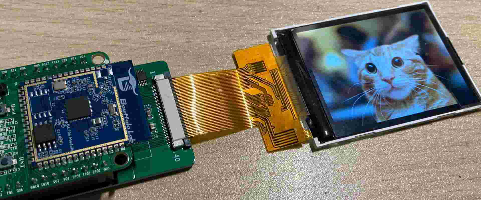
Rigid-flex boards provide electrical connections between multiple rigid circuit boards allowing them to flex and bend dynamically. This enables more efficient use of space and greater freedom when integrating PCBs into products with unique form factors and moving parts. Additionally, rigid-flex boards can reduce the need for connectors and cables which adds cost and bulk.
In this article, we will explore what rigid flex technology is, its benefits, the manufacturing process, and leading applications propelling adoption.
What are Rigid Flex Circuit Boards?
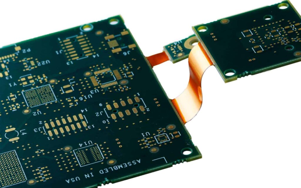
Rigid-flex boards integrate rigid substrates, like FR-4, with flexible substrates such as polyimide in a single PCB. Rigid sections provide mechanical support and leverage traditional circuit manufacturing methods. Flexible sections allow dynamic movement and three-dimensional configurations.
Here are the main elements that make up a rigid flex board:
- Rigid layers – Typically made using FR-4 material which has fiberglass reinforcement for structural rigidity. Rigid layers host surface mount technology (SMT) components and integrate complex circuitry.
- Flexible layers – Use polyimide film layers that can be bent and flexed repeatedly. Enable connections between rigid sections.
- Cover layer – Additional polyimide or adhesive outer-layers that protect circuitry.
- Bonding adhesive – Glues the rigid and flex layers together firmly.
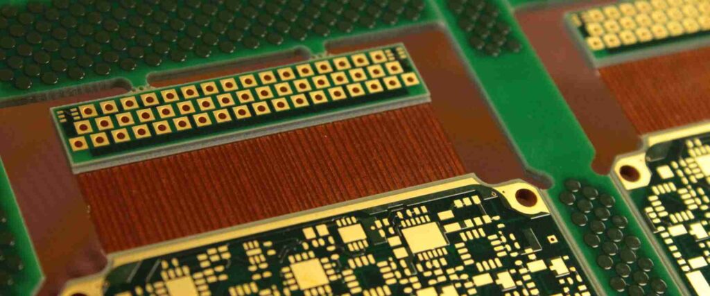
The rigid and flexible substrates are integrally laminated together in a single PCB design. Conductive materials and traces patterned on the flexible layers provide electrical connections between the rigid boards across hinges and bends.
Benefits of Rigid Flex Boards
Here are some of the top benefits rigid-flex PCB technology provides:
1. Space and Weight Savings
By folding and bending, rigid-flex boards can fit into tight spaces and complex form factors impossible with rigid PCBs. This allows for smaller and lighter electronics. With portable devices and wearables especially, rigid-flex PCBs are enabling sleek industrial designs and ergonomics.
2. Improved Reliability
The folds in rigid-flex boards experience minimal stresses during movement which enhances reliability and product life. And having a single PCB eliminates interconnects between separate rigid boards which can fail over time.
3. Reduced Assembly Costs
Rigid-flex PCBs allow components to be directly assembled onto the flexible circuit layers. This consolidation cuts down on connectors, cables, and other attachments that increase production cost and time.
4. Enhanced Manufacturability
Rigid-flex boards simplify manufacturing by reducing parts. Automated component placement and soldering is easier on a single board versus an assembly of interconnected rigid boards.
5. Supports Advanced Applications
The bending and flexing abilities of rigid-flex boards enable innovative applications such as flexible displays, wearables, medical devices, robotics, and more.
| Benefit | Description |
|---|---|
| Space/Weight Savings | Folds into tight spaces. Smaller, lighter electronics. |
| Reliability | Withstands flexing. Eliminates interconnections. |
| Reduced Assembly Cost | Fewer components to assemble. |
| Manufacturability | Automated assembly. |
| Advanced Applications | Flexible displays, wearables, etc. |
Table: Key Benefits of Rigid-Flex Boards
Rigid-Flex Board Materials and Construction
Rigid-flex PCBs can be fabricated using a range of rigid and flexible materials to meet application requirements:
Rigid Substrate Materials
- FR-4 – Fiberglass reinforced epoxy. Most common rigid substrate.
- PTFE (Teflon) – High temperature and chemical resistance.
- Isola – High performance for bandwidth. Low moisture absorption.
- Polyimide – Can operate at very high temperatures.
- Aluminum – Excellent thermal conductivity.
Flexible Substrate Films
- Polyimide (Kapton) – Strong and heat resistant. Most common flex material.
- PEEK – Withstands ultra-high temperatures.
- Polyester (PET) – Low cost. Used for simple flex applications.
The rigid and flexible materials are bonded together using adhesive layers. Common bonding adhesives include acrylic, nitrile phenolic, and epoxy. The type of adhesive controls properties like flexibility, temperature resistance, and dielectric constant.
In terms of construction, rigid-flex boards can have many configurations:
- 2-layer – Single rigid board and flex layer. Low complexity.
- Multi-layer – Multiple rigid board and flex layers. High complexity.
- Sculpted bend – Flexible material removed in bend areas. Improves flex life.
- Independent hinge – Discrete bend sections for controlled folding.
Rigid-Flex PCB Fabrication Process
Producing a rigid-flex board is an advanced process requiring specialized fabrication techniques:
1. Design – Create circuit layout integrating rigid and flex sections. SIM tools verify electrical connections.
2. Materials Prep – Cut rigid laminates. Adhere flex film layers. Control material shrinkage.
3. Imaging – Use photolithography to transfer circuit patterns onto layers.
4. Etching – Chemically etch away unwanted copper to leave circuit traces.
5. Lamination – Align layers and use heat and pressure to bond stack together.
6. Drilling – Machine holes through all layers for component pins.
7. Plating – Coat holes with copper to create conductive vias.
8. Solder mask – Apply epoxy layer over traces for insulation. Leave pads exposed.
9. Silkscreen – Print informational markings and legends on board.
10. Testing – Functionally test board. Inspect joints and bends.
Rigid-flex PCB fabrication requires specialized tools and processes to handle both rigid and flexible substrates together. This includes advanced imaging, etching, and lamination equipment.
Leading Applications of Rigid-Flex Boards
Here are some of the advanced and high-growth applications making use of rigid-flex PCB technology today:
Aerospace and Defense
Rigid-flex boards are widely used in guidance systems, avionics, radars, and other electronics for jets and missiles. The dynamic flexing abilities improve reliability in high vibration environments.
Medical Electronics
Implantable medical devices like hearing aids and pacemakers leverage rigid-flex boards to integrate microelectronics into ergonomic and bio-compatible packages.
Consumer Wearables
Foldable rigid-flex circuits enable smart watch and fitness tracker designs that can be worn comfortably on the wrist and withstand repeated flexing.
Consumer Electronics
Smartphones and tablets use rigid-flex boards to interconnect logic boards and displays, enabling sleek industrial designs.
Automotive Electronics
Advanced driver assistance systems and infotainment centers employ rigid-flex boards to embed electronics while saving space.
| Sector | Applications |
|---|---|
| Aerospace/Defense | Guidance systems, avionics |
| Medical | Implantables, hearing aids |
| Wearables | Smart watches, fitness bands |
| Consumer Electronics | Smartphones, laptops |
| Automotive | ADAS, infotainment |
Table: Leading Application Sectors for Rigid-Flex Boards
This range of cutting-edge applications highlights the value rigid-flex PCBs provide through their unique combination of rigidity and flexibility in a single board solution.
Rigid-Flex Design and Simulation Tools
To aid engineers with rigid-flex development, leading PCB software platforms provide specialized design and simulation capabilities:
Altium Designer – Unified design environment with dedicated rigid-flex features for layer stack planning, 2D/3D folding visualization, and DFM analysis.
Cadence Allegro – Complete PCB layout solution with rigid-flex design capabilities including flex modeling tools and virtual prototyping.
Mentor Xpedition – Integrated rigid flex design, DFM analysis, thermal modeling, and MCAD co-design features.
Siemens NX – Multiphysics analysis tools for optimizing rigid-flex board reliability including fatigue life modeling.
Ansys HFSSTM – Simulation tools for modeling rigid-flex PCBs under real-world mechanical, thermal, and vibration conditions.
These solutions help engineers take full advantage of rigid-flex PCB technology and accelerate time-to-market. Simulation and analysis aids component placement for reliability, modeling dynamic bending, and ensuring manufacturability.
Rigid-Flex Boards Offer Integration, Reliability and Space Savings
Rigid-flex PCBs provide a unique integration of rigid board support and flexible circuits in a single design. This opens new possibilities for electronics engineers facing space and wiring challenges. Rigid-flex boards are enabling cutting-edge applications thanks to their reliability, compactness, and manufacturability versus traditional rigid boards linked by cables and connectors.
Continued innovation in rigid-flex materials, fabrication methods, and design tools will expand adoption across consumer and industrial electronics. As products demand more advanced functionality in smaller spaces, rigid-flex PCBs present an ideal solution that combines the best of both worlds.
Frequently Asked Questions
What are some key differences when designing rigid-flex boards versus traditional rigid PCBs?
Some key rigid-flex design considerations include:
- Planning the layer stack with both rigid and flex layers
- Minimizing components around bend areas
- Allowing sufficient space for folds and bends
- Specifying materials compatible with flexing
- Capturing folding information for manufacturing
- Simulating mechanical stress and fatigue life
What types of testing are done to qualify rigid-flex boards?
Typical rigid-flex qualification tests include:
- Visual inspection of layer alignment
- Continuity testing of traces
- Hinge/bend cycle testing for durability
- Vibration testing to simulate environments
- Thermal cycling from temperature extremes
- Electrical testing at temperature and under bend
- Cross-section examination of layer adhesion
Can off-the-shelf rigid and flex materials be combined when making rigid-flex boards?
Generally no, combining rigid and flex materials sourced from different suppliers is not recommended. The board fabrication process requires tight control of material properties to ensure proper adhesion, dimensional stability, and performance. Leading rigid-flex manufacturers have selectively engineered material sets that are optimized to work together.
What types of connectors can be used with rigid-flex boards?
Common connectors used with rigid-flex PCBs include:
- Board-to-board connectors bridging separate rigid sections
- FPC (flexible printed circuit) connectors attaching flex tails
- ZIF/LIF (zero/low insertion force) connectors on flex sections
- Flex-rigid connectors allowing flex bending
- SMT (surface mount) connectors soldered to rigid sections
Which key factors determine the minimum bend radius on a rigid-flex board?
The minimum bend radius depends on:
- Thickness of the flex laminate
- Number of flex layer in the bend area
- Properties of the flex material
- Copper thickness around the bend
- Dynamic or static bend requirements
Tighter bend radii allow more compact rigid-flex board designs but require advanced engineering.
Conclusion
Rigid-flex PCB technology enables electronics designers to overcome complex integration and space constraints through clever combinations of rigid boards and dynamic flex circuits. Component integration, reliability, size reduction, and manufacturability are driving adoption across cutting-edge product segments.
Continued advances in materials, fabrication methods, and design tools will further improve rigid-flex capabilities and expand adoption. Engineers now have tremendous design freedom to optimize the placement of electronics by combining the stability of defined PCB sections with the dynamic flexibility of polyimide films. Rigid-flex boards deliver integration opportunities not possible with traditional approaches, allowing the electronics and industrial products of tomorrow to achieve new heights of performance in ever-shrinking packages.


Leave a Reply