Introduction
Printed circuit boards (PCBs) are essential components in nearly all modern electronics. They provide the physical structure and electrical connections between the various components that make up an electronic device. There are two main types of PCBs: rigid and flexible. Both have their own advantages and applications. This article will examine the key differences between rigid and flexible PCBs, their manufacturing processes, and when each one is the optimal choice.
Rigid vs Flexible PCBs
What are Rigid PCBs?
Rigid PCBs were the original type of printed circuit board invented in the 1950s. As the name implies, rigid PCBs are stiff, flat boards made of insulating material clad with strips of copper that serve as the conductive paths between components. The most common base material is FR-4 fiberglass, which provides mechanical rigidity and heat resistance. Other rigid PCB materials include CEM-1, CEM-3, FR-2, G-10, and polyimide.
Rigid PCBs provide a sturdy structural foundation for electronic circuits. They are suitable for products where the PCB itself serves as the chassis or enclosure. Rigid PCBs maintain their shape under mechanical stress, allowing them to be populated with heavy components. The rigidity also aids in dissipating heat from heat-generating parts.
What are Flexible PCBs?
Flexible PCBs were introduced in the 1960s and are sometimes called “flex circuits.” As the name states, flex PCBs can bend, fold, and flex. This allows them to be wrapped around edges or molded to fit unique product enclosures.
The most common base material for flex PCBs is polyimide, a flexible plastic polymer. Other materials include polyester, polyetherimide, and PEEK. Flex PCBs use extremely thin copper traces, allowing them to bend repeatedly without damage. Special dielectric bonding films and cover layers provide insulation and protect traces.
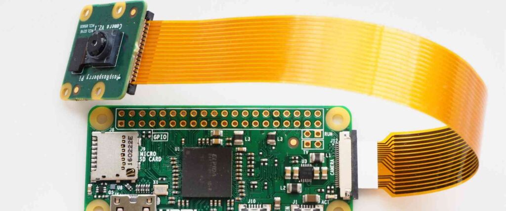
Flexible PCBs are ideal when the application requires dynamic movement, complex 3D routing, or fitting PCBs into tight spaces. The ability to bend and flex makes them well-suited for products like cameras, wearables, medical devices, and consumer electronics.
Key Differences
Here are some of the main differences between rigid and flexible PCBs:
- Rigidity: Rigid PCBs are stiff and inflexible. Flex PCBs can bend, fold, and flex repeatedly.
- Base material: Rigid PCBs typically use FR-4 fiberglass. Flex PCBs use polyimide or other flexible plastics.
- Trace thickness: Rigid PCB traces are thicker, around 1 oz (35 micron) copper. Flex PCB traces are extremely thin, around 1/4 to 1/2 oz (8-18 micron) copper.
- Environmental resistance: Rigid PCBs withstand higher temperatures. Flex PCBs are more prone to issues from repeated bending.
- Density: Rigid PCBs support higher complexity and component density. Flex PCBs have limitations on trace spacing and thinness.
- Applications: Rigid PCBs are used widely across all electronics. Flex PCBs suit products where flexibility, space savings, or complex routing are required.
Manufacturing Processes
Rigid and flexible PCBs follow somewhat different manufacturing sequences:
Rigid PCB Fabrication
The standard process steps in making a rigid PCB include:
- Design and layout – Done with CAD software like Altium, Eagle, KiCAD, etc.
- Prototyping – Making smaller quantities of preliminary boards to test the design.
- Fabrication – Creating the physical PCB with the following steps:
- Lamination – Stacking and bonding together the core and prepreg layers.
- Drilling – Using tiny drill bits to create holes for vias and component leads.
- Metallization – Electroplating copper to coat the inside walls of drilled holes.
- Imaging – Coating with photoresist, exposing the resist, then developing to form an etch mask.
- Etching – Removing exposed copper to leave only the desired traces protected by photoresist.
- Stripping – Removing excess photoresist.
- Solder mask & silkscreen – Applying epoxy layers for insulation and labelling.
- Surface finish – Coating exposed copper traces to protect against oxidation. Common finishes are HASL, ENIG, Immersion Silver, etc.
- Electrical testing – Testing for shorts, opens, and verifying PCB function.
- Assembly – Populating the PCB with electronic components to build the finished circuit board assembly (CBA).
Flex PCB Fabrication
Flex PCBs undergo a similar set of process steps, with a few key differences:
- Materials – Using flexible base materials like polyimide instead of rigid FR-4.
- Buildup – Flex PCBs use a additive process to build up layers, instead of laminating multilayer boards.
- Etching – Etchants used must be compatible with flex materials.
- Patterning – Photoresist may be applied in a roll-to-roll process rather than panels.
- Via formation – Microvias are made with laser drilling, then plated like rigid PCB drilling.
- Stiffeners – A rigid stiffener may be added to aid assembly and protect traces.
- Bonded layers – Flexible materials are adhesively bonded versus fusion bonding.
Rigid vs. Flexible PCB: How to Choose
Here are some guidelines on when to choose a rigid PCB versus when a flexible PCB would be more suitable:
When to Choose Rigid PCBs
- High component density and complex circuitry
- When the PCB will serve as a structure or enclosure
- For rugged, high temperature, or high vibration environments
- When the product itself will not flex or bend significantly
- When lower cost is critical
When to Choose Flexible PCBs
- When the PCB needs to flex, wrap, or bend
- For space-constrained or complex 3D routings
- When the PCB will experience dynamic flexing during use
- For products where flexibility is a key requirement
- When layer counts are low (2 to 6 layers typical)
Here are some examples of products that typically utilize flexible PCBs:
- Wearable devices (smart watches, fitness bands, health sensors)
- Mobile phones, tablets, laptops
- Digital cameras
- Printers, scanners
- Medical equipment
- Automotive electronics
- IoT devices
- Robotics
And applications where rigid PCBs are very common:
- Computers (desktops, servers)
- Industrial control systems
- Measurement equipment
- Wireless infrastructure (access points, routers, etc.)
- LED lighting
- Consumer appliances
In some cases, products may incorporate both rigid and flex PCBs to leverage the benefits of both. The rigid PCB hosts the complex circuitry, while the flex PCB provides dynamic interconnections.
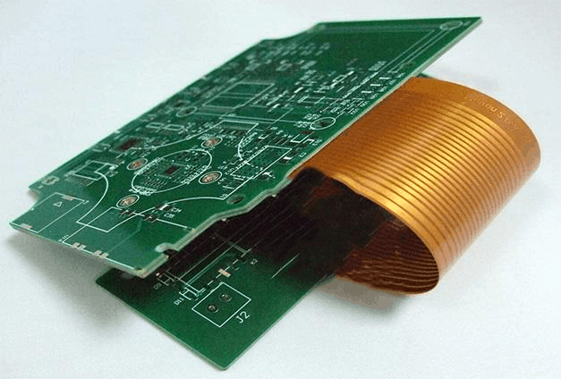
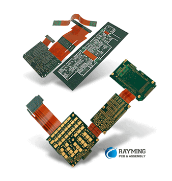
Flex-Rigid PCBs
Flex-rigid PCBs combine rigid FR-4 material with flexible polyimide or Kapton layers. This allows a single PCB solution to have both rigid areas for components and mounting, along with flexible sections to bend and route through hinges or dynamic areas.
The rigid and flex layers are adhesively bonded together. Flex-rigid PCBs provide an optimal combo of density, rigidity, and flexibility in one design. They are ideal when a design has demanding electronics as well as the need for motion or complex routing.
Rigid-Flex PCB Fab & Design Tips
Here are some tips for working with rigid-flex PCBs:
Fabrication Notes
- Work closely with your PCB manufacturer during design, as flex-rigid introduces additional fabrication steps.
- Allow for larger tolerances – around 0.2mm for features like outlines and cutouts.
- Use stress relief features in flex-to-rigid transition areas.
- Minimize rigid layers to reduce thickness and improve reliability.
Design Considerations
- Clearly define outlines for rigid vs. flex sections.
- Route signals selectively – high speed, RF on rigid portions, lower speed to flex areas.
- Stiffeners can help manage flex layers during assembly and protect traces.
- Model flexibility to ensure dynamic bending does not over-stress traces.
- Limit components mounted on flex layers to avoid cracking solders.
The Future of Flexible PCBs
Flexible PCBs have become a major part of the electronics landscape, especially with growth in consumer wearables and Internet of Things devices. Flex PCB usage will likely continue expanding as designers place greater emphasis on ergonomics, conformality, and lightweight products.
At the same time, advances in flexible PCB materials, fabrication processes, and design tools will enable more complex and reliable flexible circuits. Flex-rigid PCBs will also become more capable and utilized in designs.
Some key trends influencing flex PCB advancement:
- New flexible base materials – For example, flexible glass substrates.
- Higher density interconnect – Finer features and spacing to increase trace density.
- Better modeling and simulation – Tools to improve first-pass design success.
- Innovation in flexible component packaging – Bendable integrated circuits and connectors.
- 3D printing and additive flex PCB fabrication – Enabling custom geometries and rapid prototyping.
- Growth of consumer wearables and IoT – Driving demand for flex and flex-rigid PCBs.
Frequently Asked Questions
What are some typical rigid PCB thicknesses?
Common rigid PCB thicknesses range from about 0.4mm (1/64″) for 2-layer boards up to around 1.6mm (1/16″) for high layer count multilayer boards. Some specialized rigid PCBs can go up to 3.2mm (1/8″) thick.
How many layers can rigid PCBs support?
Modern rigid PCBs can incorporate over 30 conductive layers, though 8-16 layers is typical for complex designs. Rigid PCBs can support higher layer counts than flexible PCBs.
What are the most common flexible PCB thicknesses?
Simple 2-layer flex PCBs often use 25micron (1 mil) polyimide. More complex flex PCBs range from 50microns (2 mil) to around 150microns (6 mil) thick.
Is it possible to mount components on flexible PCBs?
Yes, though components on flex PCBs should be small and lightweight. Avoid large connectors or tall components. Use flexible solders and adhesives to prevent cracking. Provide strain relief to components in high-flex areas.
How do you protect flexible PCB traces from damage?
Careful mechanical design is key. Ensure sufficient bend radius for dynamic areas. Avoid high-flex zones under components. Use adhesive stiffeners over high-density interconnects. Encapsulate the flex PCB with plastic films. Limit free-hanging flex segments.
Conclusion
Rigid and flexible PCBs each offer unique advantages that make them suitable for different applications. Rigid PCBs provide structural stability for complex, dense circuitry and can withstand rugged conditions. Flexible PCBs enable dynamic flexing, 3D routing, and conformal designs.
Understanding the core differences in materials, manufacturing, performance, and designs will help product creators select the best PCB technology for their application needs. With the continuing advancement of fabrication processes and design tools, both rigid and flexible PCBs will remain indispensable foundations of electronic products.


Leave a Reply