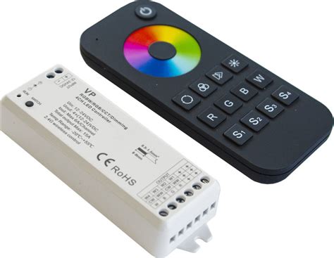
What is an RGB Controller?
An RGB controller is an electronic circuit that controls the color and brightness of RGB (Red, Green, Blue) LEDs. By varying the intensity of the red, green, and blue elements, an RGB controller can generate millions of different colors. RGB controllers take input, either from a microcontroller or manual controls like buttons and knobs, and output PWM signals to the red, green, and blue anodes of the RGB LEDs to set the color.
RGB controllers range from simple, manually-controlled circuits to complex controllers with microprocessors and wireless connectivity that can control large numbers of LEDs. They are used in a wide variety of applications including accent lighting, displays, automotive lighting, stage lighting and more.
How Does an RGB Controller Work?
PWM Control of RGB LEDs
RGB controllers work by using pulse-width modulation (PWM) to control the brightness of the red, green, and blue elements in an RGB LED. By rapidly pulsing each element on and off and varying the duty cycle (ratio of on-time to off-time), the perceived brightness of each color can be changed. The duty cycles for the red, green, and blue elements determine the output color.
For example, here are some common colors and their approximate PWM duty cycle percentages:
| Color | Red | Green | Blue |
|---|---|---|---|
| Red | 100% | 0% | 0% |
| Green | 0% | 100% | 0% |
| Blue | 0% | 0% | 100% |
| Yellow | 100% | 100% | 0% |
| Purple | 50% | 0% | 50% |
| White | 100% | 100% | 100% |
By outputting the appropriate PWM signals to the red, green, and blue anodes of the LED, the RGB controller can set it to any color within the LED’s gamut.
RGB LED Drivers
To control high-power RGB LEDs or large numbers of LEDs, an RGB controller needs LED driver circuits. A constant current LED driver provides a fixed current to the LED, which is needed for consistent brightness and to avoid damaging the LED. LED drivers take a PWM input and provide a proportional current output.
There are many dedicated constant current LED driver chips available that simply need a PWM input and can drive large currents. Common chips include:
- TLC5940 – 16 channel, 12-bit PWM, 120mA/channel
- PCA9685 – 16 channel, 12-bit PWM, 25mA/channel, I2C interface
- WS2803 – 18 channel, 8-bit PWM, 30mA/channel, daisy-chainable
These drivers can be cascaded to control large numbers of RGB LEDs from a single microcontroller.
Microcontroller-Based RGB Controllers
Many RGB controllers use a microcontroller to generate the PWM control signals and provide features like:
- Multiple lighting patterns and sequences
- Color fading and breathing effects
- Configurable speed and brightness
- Remote control via buttons, IR, bluetooth, wifi, etc.
A microcontroller-based RGB controller typically has the following elements:
- Microcontroller (Arduino, PIC, ESP32, etc.)
- Constant current RGB LED drivers
- Power supply (5V or 12V typical)
- Input controls (buttons, knobs, IR receiver, etc.)
- Output connectors for the RGB LEDs
The microcontroller runs a program that reads the input controls, selects colors and patterns from pre-programmed options or based on user input, and outputs the corresponding PWM signals to the LED drivers.

How to Make an RGB Controller
Now that we know how RGB controllers work, let’s look at how to make a simple 1-channel RGB controller based on an Arduino Nano microcontroller. This controller will allow setting the RGB LED color via potentiometer knobs.
Parts Needed
- Arduino Nano
- 3x 10K potentiometers
- Breadboard
- Jumper wires
- Common anode RGB LED
- 3x 220 ohm resistors
- USB mini-B cable
Circuit Diagram
Here is the circuit diagram for the Arduino RGB controller:
[Circuit diagram image]
The three potentiometers connect to analog inputs A0-A2 on the Arduino and act as voltage dividers providing a variable voltage from 0-5V. The Arduino reads these voltages and uses them to set the PWM duty cycle percentages for the red, green, and blue LED elements.
Digital I/O pins D9, D10, D11 output the PWM signals through 220 ohm current limiting resistors to the red, green and blue anodes of the common-anode RGB LED. The Arduino sketch scales the 0-5V input voltages to 0-255 for the PWM duty cycle.
Arduino Sketch
Here is the Arduino sketch to read the potentiometers and control the RGB LED:
const int redPin = 9;
const int greenPin = 10;
const int bluePin = 11;

const int redIn = A0;
const int greenIn = A1;
const int blueIn = A2;

void setup() {
  pinMode(redPin, OUTPUT);
  pinMode(greenPin, OUTPUT);
  pinMode(bluePin, OUTPUT);
}

void loop() {
  int redValue = map(analogRead(redIn), 0, 1023, 0, 255);
  int greenValue = map(analogRead(greenIn), 0, 1023, 0, 255);
  int blueValue = map(analogRead(blueIn), 0, 1023, 0, 255);

  analogWrite(redPin, redValue);
  analogWrite(greenPin, greenValue);
  analogWrite(bluePin, blueValue);
}
The map() function scales the 10-bit ADC values from the potentiometers (0-1023) to 8-bit PWM values (0-255). The analogWrite() functions set the PWM duty cycles on the red, green, and blue pins.
Constructing the Circuit
To build the circuit:
- Plug the Arduino Nano into the breadboard
- Connect the potentiometers to 5V, GND, and A0, A1, A2 on the Arduino
- Connect 220 ohm resistors from D9, D10, D11 to the red, green, blue pins of the RGB LED
- Connect the common anode of the LED to 5V
- Upload the sketch to the Arduino
Adjusting the potentiometers will now change the color of the RGB LED!

Frequently Asked Questions
What’s the difference between common anode and common cathode RGB LEDs?
Common anode RGB LEDs have a shared anode (positive) connection, while common cathode have a shared cathode (negative). With common anode, the PWM signals connect to the cathodes and pull to ground to turn on. With common cathode, the PWM goes to the anodes. Most RGB controllers work with either type, but the wiring and code are slightly different.
How many RGB LEDs can one controller control?
It depends on the controller design and the LED current requirements. A simple Arduino controller with PWM outputs can directly drive a single RGB LED. To control more LEDs, you need constant current LED drivers. Drivers are available that can control 16 or more LEDs each and can be chained to control large LED arrays from one microcontroller.
What’s the advantage of digital RGB LEDs like WS2812B?
Digital RGB LEDs have an integrated driver chip and are daisy-chained, so they only require a single data signal from the controller. This allows controlling large numbers of RGB LEDs without complex wiring. The trade-off is they require precise timing of the data signal and can be more complex to program.
Can I control RGB LEDs with a Raspberry Pi?
Yes, a Raspberry Pi can work as an RGB controller. It has PWM outputs to directly drive RGB LEDs. You can also connect I2C or SPI LED drivers to control larger numbers. The Raspberry Pi is good for standalone installations that may need to do video processing, respond to sensors, or connect to the internet.
How do I power large numbers of RGB LEDs?
Powering large RGB LED installations requires careful power supply design. Each LED can draw 20mA or more per color channel. A 5 meter, 60 LED/meter strip can use close to 9A at full brightness white. A constant voltage power supply of sufficient current rating for the number of LEDs is needed. The power supply positive connects to all the LED anodes (or V+ input for digital LEDs) and negative to the controller and LED driver grounds. The RGB LED controller then switches the negative side of the LEDs.
I hope this article has helped explain RGB LED controllers and how to get started making your own controller for your RGB LED projects! Let me know if you have any other questions.


Leave a Reply