Introduction to RF Amplifier Design
Radio Frequency (RF) amplifiers are essential components in wireless communication systems, responsible for amplifying weak signals to enable effective transmission and reception. Designing an RF amplifier involves careful consideration of various factors such as frequency range, gain, linearity, noise figure, and power efficiency. In this article, we will explore the key steps involved in designing an RF amplifier, providing insights into the design process and best practices.
Step 1: Determine the Specifications
Frequency Range
The first step in designing an RF amplifier is to determine the frequency range of operation. This is crucial as it affects the choice of components, circuit topology, and overall performance. Consider the specific application and the corresponding frequency band, such as:
- VHF (Very High Frequency): 30 MHz to 300 MHz
- UHF (Ultra High Frequency): 300 MHz to 3 GHz
- Microwave: 3 GHz and above
Gain and Output Power
Next, define the required gain and output power of the amplifier. The gain, expressed in decibels (dB), represents the ratio of the output signal power to the input signal power. The output power, typically measured in watts (W) or dBm, determines the maximum signal strength the amplifier can deliver.
Consider the following factors when specifying the gain and output power:
- Signal strength of the input signal
- Desired signal strength at the output
- Power handling capability of the load (e.g., antenna)
Linearity and Distortion
Linearity is a critical aspect of RF amplifier design, as it determines the amplifier’s ability to accurately reproduce the input signal without introducing distortion. Nonlinearity can cause intermodulation distortion (IMD), resulting in unwanted frequency components and degraded signal quality.
Define the linearity requirements based on the application:
- 1 dB compression point (P1dB): The output power level at which the gain drops by 1 dB from its small-signal value
- Third-order intercept point (IP3): A measure of the amplifier’s ability to handle multiple signals without generating excessive intermodulation products
Noise Figure
The noise figure (NF) quantifies the amount of noise introduced by the amplifier, which can degrade the signal-to-noise ratio (SNR) of the system. A lower noise figure indicates better noise performance.
Determine the acceptable noise figure based on the system requirements and the expected signal levels.

Step 2: Select the Transistor
The choice of transistor is a critical decision in RF amplifier design. The transistor’s characteristics, such as frequency range, gain, linearity, and power handling capability, directly impact the amplifier’s performance.
Transistor Technologies
Consider the following transistor technologies for RF amplifier design:
- Bipolar Junction Transistors (BJTs): Suitable for low-noise and low-power applications
- Field-Effect Transistors (FETs): Commonly used for high-frequency and high-power applications
- MOSFETs (Metal-Oxide-Semiconductor FETs)
- HEMTs (High Electron Mobility Transistors)
Key Parameters
When selecting a transistor, evaluate the following key parameters:
- Transit frequency (fT): The frequency at which the current gain drops to unity
- Maximum oscillation frequency (fmax): The maximum frequency at which the transistor can provide power gain
- Breakdown voltage (BVCEO): The maximum collector-emitter voltage the transistor can withstand
- Output power and efficiency
- Noise figure

Step 3: Design the Biasing Network
Proper biasing of the transistor is essential for optimal performance and stability. The biasing network establishes the operating point of the transistor, ensuring it operates in the desired region (e.g., active, saturation, or cutoff).
Bias Topologies
Consider the following bias topologies for RF amplifiers:
- Fixed bias: Provides a constant DC voltage to the transistor’s base or gate
- Self-bias: Utilizes a resistive divider network to set the bias point automatically
- Active bias: Employs an additional transistor or integrated circuit to control the bias point
Bias Stability
Ensure the biasing network provides stable operation over temperature variations and supply voltage fluctuations. Use temperature compensation techniques, such as thermistors or diodes, to maintain a consistent bias point.
Bias Decoupling
Include appropriate decoupling capacitors in the biasing network to prevent RF signals from entering the DC bias lines and causing instability or distortion.

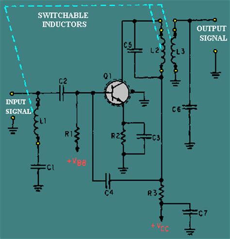
Step 4: Design the Matching Networks
Matching networks are used to maximize power transfer, improve efficiency, and ensure proper impedance matching between the transistor and the input/output loads.
Input Matching Network
The input matching network transforms the input impedance of the transistor to match the source impedance (e.g., 50 ohms). Proper input matching minimizes reflections and ensures maximum power transfer from the source to the amplifier.
Consider the following techniques for input matching:
- Lumped element matching: Uses discrete components (inductors and capacitors) to achieve impedance transformation
- Microstrip matching: Employs transmission line sections on a printed circuit board (PCB) for impedance matching
Output Matching Network
The output matching network transforms the transistor’s output impedance to match the load impedance, typically 50 ohms. Proper output matching maximizes power transfer to the load and minimizes reflections.
Similar to input matching, output matching can be achieved using lumped elements or microstrip lines.
Stability Considerations
Ensure the amplifier remains stable across the desired frequency range. Unstable operation can lead to oscillations and degraded performance.
Use stability analysis techniques, such as the Rollett stability factor (K-factor) or the Nyquist stability criterion, to assess the amplifier’s stability. Implement stabilization techniques, such as resistive loading or feedback networks, if necessary.
Step 5: Simulate and Optimize
Before fabricating the RF amplifier, perform comprehensive simulations to evaluate its performance and optimize the design.
Simulation Tools
Use industry-standard simulation tools, such as:
- Keysight ADS (Advanced Design System)
- Cadence Virtuoso
- NI AWR Design Environment
These tools allow for accurate modeling of the transistor, passive components, and transmission lines, enabling realistic simulations of the amplifier’s behavior.
Simulation Setup
Set up the simulation environment by:
- Creating a schematic of the RF amplifier, including the transistor, biasing network, and matching networks
- Defining the simulation frequency range and desired performance metrics (gain, output power, linearity, etc.)
- Specifying the component models and their parameters
Optimization
Iterate the design by adjusting component values, transistor sizing, and matching network topologies to achieve the desired performance. Utilize optimization algorithms, such as gradient-based or genetic algorithms, to fine-tune the design parameters.
Evaluate the simulated results against the target specifications and make necessary adjustments until the desired performance is achieved.
Conclusion
Designing an RF amplifier involves careful consideration of specifications, transistor selection, biasing, matching networks, and simulation-driven optimization. By following these five steps and adhering to best practices, engineers can develop high-performance RF amplifiers tailored to specific applications.
Remember to consider factors such as frequency range, gain, linearity, noise figure, and power efficiency throughout the design process. Utilize industry-standard simulation tools to validate and optimize the design before proceeding to fabrication and testing.
With a well-designed RF amplifier, wireless communication systems can benefit from enhanced signal strength, improved signal quality, and extended transmission range.
Frequently Asked Questions (FAQ)
1. What is the purpose of an RF amplifier?
An RF amplifier is designed to increase the power of a radio frequency (RF) signal. It takes a weak RF signal as input and amplifies it to a higher power level, enabling effective transmission and reception in wireless communication systems.
2. What are the key specifications to consider when designing an RF amplifier?
When designing an RF amplifier, the key specifications to consider include:
– Frequency range
– Gain
– Output power
– Linearity (e.g., 1 dB compression point, third-order intercept point)
– Noise figure
– Power efficiency
These specifications are determined based on the specific application and system requirements.
3. What are the commonly used transistor technologies for RF amplifiers?
The commonly used transistor technologies for RF amplifiers include:
– Bipolar Junction Transistors (BJTs): Suitable for low-noise and low-power applications
– Field-Effect Transistors (FETs):
– MOSFETs (Metal-Oxide-Semiconductor FETs): Widely used for high-frequency and high-power applications
– HEMTs (High Electron Mobility Transistors): Offering high gain and low noise performance
The choice of transistor technology depends on the desired frequency range, power handling capability, and performance requirements.
4. Why is proper biasing important in RF amplifier design?
Proper biasing is crucial in RF amplifier design for the following reasons:
– It sets the operating point of the transistor, ensuring it operates in the desired region (active, saturation, or cutoff)
– It provides stable operation over temperature variations and supply voltage fluctuations
– It helps achieve optimal performance in terms of gain, linearity, and efficiency
Improper biasing can lead to distortion, instability, and degraded amplifier performance.
5. What is the purpose of matching networks in an RF amplifier?
Matching networks serve the following purposes in an RF amplifier:
– Input matching network: Transforms the input impedance of the transistor to match the source impedance, ensuring maximum power transfer and minimizing reflections
– Output matching network: Transforms the transistor’s output impedance to match the load impedance, maximizing power transfer to the load and minimizing reflections
Proper matching networks are essential for optimizing power transfer, improving efficiency, and ensuring stable operation of the RF amplifier.


Leave a Reply