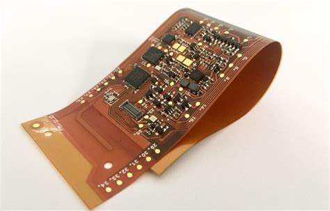
What is a Rigid-Flex PCB?
A Rigid-Flex PCB is a printed circuit board that combines both rigid and flexible substrates. The rigid portions of the board provide structural support and house the majority of the components, while the flexible portions allow for bending and folding, enabling more compact and versatile designs.
The flexible sections of a Rigid-Flex PCB are typically made of thin, flexible materials such as polyimide or polyester. These materials are laminated together with conductive layers, usually copper, to create the circuit pattern. The rigid sections, on the other hand, are made of standard PCB materials like FR-4.
Advantages of Rigid-Flex PCBs
Rigid-Flex PCBs offer several advantages over traditional rigid PCBs:
-
Space Savings: By allowing the PCB to bend and fold, Rigid-Flex PCBs enable more compact designs, saving valuable space in electronic devices.
-
Reduced Weight: The use of flexible materials and the elimination of connectors and cables reduce the overall weight of the PCB Assembly.
-
Increased Reliability: Rigid-Flex PCBs minimize the need for connectors and cables, reducing the number of potential failure points and improving overall reliability.
-
Enhanced Signal Integrity: The shorter signal paths and reduced number of interconnects in Rigid-Flex PCBs lead to improved signal integrity and reduced electromagnetic interference (EMI).
-
Design Flexibility: Rigid-Flex PCBs allow for more creative and efficient layouts, enabling designers to optimize the placement of components and routing of traces.
Applications of Rigid-Flex PCBs
Rigid-Flex PCBs find applications in a wide range of industries and products, including:
- Aerospace and Defense
- Medical Devices
- Automotive Electronics
- Consumer Electronics
- Wearable Technology
- Industrial Automation
Some specific examples of Rigid-Flex PCB applications include:
- Aerospace: Avionics systems, satellite communications, and space exploration equipment
- Medical: Implantable devices, medical imaging systems, and portable monitoring devices
- Automotive: Advanced driver assistance systems (ADAS), infotainment systems, and engine control units (ECUs)
- Consumer Electronics: Smartphones, tablets, laptops, and gaming devices
- Wearable Technology: Smartwatches, fitness trackers, and augmented reality glasses
- Industrial Automation: Robotics, machine vision systems, and process control equipment

RAYPCB’s Rigid-Flex PCB Manufacturing Capabilities
RAYPCB offers a comprehensive range of Rigid-Flex PCB manufacturing services to meet the diverse needs of our customers. Our capabilities include:
Layer Counts and Thickness
| Layer Count | Thickness Range |
|---|---|
| 2-6 Layers | 0.2mm – 2.0mm |
| 8-12 Layers | 0.8mm – 3.2mm |
| 14+ Layers | 1.6mm – 4.0mm |
Material Options
RAYPCB supports a variety of materials for Rigid-Flex PCBs, including:
- Polyimide (PI) for the flexible sections
- FR-4, High Tg FR-4, and Rogers materials for the rigid sections
- Copper foils with thicknesses ranging from 0.5 oz to 2 oz
Minimum Feature Sizes
| Feature | Minimum Size |
|---|---|
| Line Width/Spacing | 3 mil/3 mil |
| Via Diameter | 6 mil |
| Annular Ring | 4 mil |
| Hole Diameter | 8 mil |
| Solder Mask Opening | 4 mil |
| Silkscreen Line Width | 5 mil |
Surface Finishes
RAYPCB offers a variety of surface finishes for Rigid-Flex PCBs, including:
- HASL (Hot Air Solder Leveling)
- ENIG (Electroless Nickel Immersion Gold)
- Immersion Silver
- Immersion Tin
- OSP (Organic Solderability Preservative)
Quality Control and Testing
To ensure the highest quality and reliability of our Rigid-Flex PCBs, RAYPCB employs strict quality control measures and advanced testing techniques, such as:
- Automated Optical Inspection (AOI)
- X-ray Inspection
- Electrical Testing
- Microsectioning
- Thermal Cycling
- Bend Testing

Rigid-Flex PCB Design Considerations
Designing a Rigid-Flex PCB requires careful consideration of several factors to ensure optimal performance and manufacturability. Some key design considerations include:
Bend Radius and Bend Cycle
The bend radius is the minimum radius at which the flexible portion of the PCB can be bent without causing damage or affecting performance. It is essential to adhere to the manufacturer’s recommended bend radius to ensure the longevity and reliability of the Rigid-Flex PCB.
The bend cycle refers to the number of times the flexible portion of the PCB can be bent before failure. Designers should consider the expected number of bend cycles in the application and select materials and design parameters accordingly.
Stiffener Placement
Stiffeners are used in Rigid-Flex PCBs to provide additional support and rigidity to the flexible sections. Proper placement of stiffeners is crucial to prevent excessive stress on the flexible portions during bending and to maintain the desired shape of the PCB assembly.
Coverlay and Adhesive Selection
Coverlay is a protective layer applied to the flexible portions of the PCB to insulate and protect the exposed conductors. The choice of coverlay material and thickness depends on the application requirements, such as flexibility, durability, and environmental resistance.
Adhesives are used to bond the flexible and rigid sections of the PCB together. Selecting the appropriate adhesive is essential to ensure good adhesion, flexibility, and thermal stability.
Trace Routing and Via Placement
When routing traces on a Rigid-Flex PCB, designers should follow these guidelines:
- Avoid routing traces perpendicular to the bend direction to minimize stress on the conductors
- Use curved traces instead of sharp angles to reduce stress concentration
- Maintain consistent trace width and spacing throughout the flexible sections
- Place vias away from the bend areas to prevent cracking and failure
Component Placement
Component placement on a Rigid-Flex PCB should take into account the following considerations:
- Place components on the rigid sections whenever possible to minimize stress on the flexible portions
- Avoid placing large or heavy components near the bend areas
- Use surface mount components instead of through-hole components in the flexible sections to reduce the risk of via cracking
- Consider the orientation of components relative to the bend direction to minimize stress

RAYPCB’s Rigid-Flex PCB Design Support
RAYPCB offers comprehensive design support services to help customers optimize their Rigid-Flex PCB designs for manufacturability and performance. Our experienced engineers can assist with:
- Design rule checks (DRC)
- Signal integrity analysis
- Thermal analysis
- Mechanical stress analysis
- Prototyping and testing
We work closely with our customers to ensure that their Rigid-Flex PCB designs meet their specific requirements and are ready for high-volume production.
Frequently Asked Questions (FAQ)
-
What is the minimum bend radius for a Rigid-Flex PCB?
The minimum bend radius depends on the thickness and material of the flexible portion of the PCB. As a general rule, the minimum bend radius should be at least 6 times the thickness of the flexible material. However, it is always best to consult with your PCB manufacturer for specific recommendations. -
Can Rigid-Flex PCBs be used in high-temperature environments?
Yes, Rigid-Flex PCBs can be designed to withstand high-temperature environments. The choice of materials, such as polyimide for the flexible portions and high Tg FR-4 for the rigid sections, can help ensure the PCB’s stability and reliability in high-temperature applications. -
How do I determine the number of layers needed for my Rigid-Flex PCB?
The number of layers in a Rigid-Flex PCB depends on the complexity of the circuit, the number of components, and the routing requirements. As a general guideline, simple designs may require 2-6 layers, while more complex designs may need 8-12 layers or more. It is best to work with your PCB manufacturer to determine the optimal layer count for your specific application. -
What is the typical lead time for Rigid-Flex PCBs?
The lead time for Rigid-Flex PCBs can vary depending on the complexity of the design, the materials used, and the manufacturer’s workload. At RAYPCB, our typical lead time for Rigid-Flex PCBs is 3-4 weeks for prototypes and 4-6 weeks for production quantities. However, we always strive to meet our customers’ specific lead time requirements whenever possible. -
How do I get started with designing a Rigid-Flex PCB?
To get started with designing a Rigid-Flex PCB, follow these steps: -
Define your application requirements, including size constraints, electrical performance, and environmental conditions.
- Create a schematic design of your circuit, specifying components and interconnections.
- Develop a mechanical layout of your PCB, considering component placement, bend locations, and layer stackup.
- Work with your PCB manufacturer to review your design, ensure manufacturability, and make any necessary adjustments.
- Create the final PCB layout, generating Gerber files and other necessary production files.
RAYPCB’s design support team is available to assist you throughout the entire process, from concept to production.
Conclusion
Rigid-Flex PCBs offer a unique combination of flexibility and rigidity, enabling more compact, lightweight, and reliable electronic devices across a wide range of industries. RAYPCB’s state-of-the-art manufacturing capabilities and experienced design support team make us the ideal partner for your Rigid-Flex PCB needs.
By understanding the benefits, applications, design considerations, and manufacturing process of Rigid-Flex PCBs, you can unlock new possibilities for your electronic designs. Contact RAYPCB today to learn more about our Rigid-Flex PCB services and how we can help bring your ideas to life.


Leave a Reply