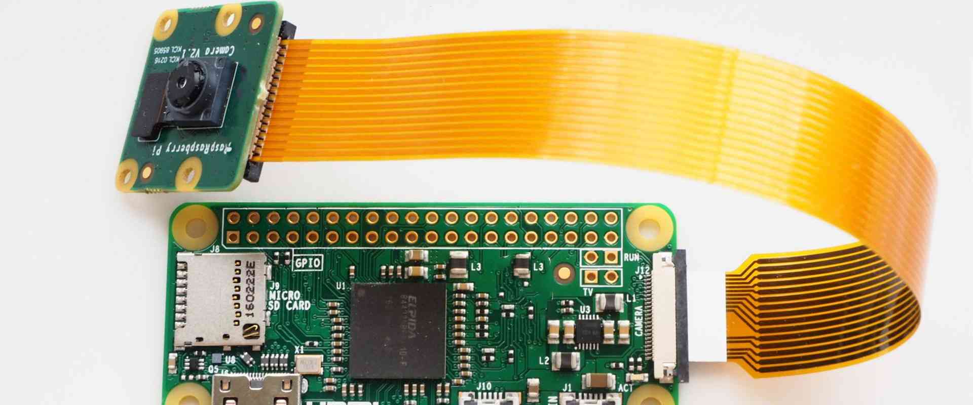
Flexible printed circuit boards (FPCBs) have become an increasingly popular solution for electronics that require dynamic flexing, folding, or bending. Rigid-flex PCBs combine rigid circuit board sections with flexible circuits linking them together. This allows for electronics that need both solid component mounting and dynamic flexibility in certain areas.
Quick turn rigid flex PCB prototypes bridge the gap between initial design and full production. They provide functional samples built to your exact specifications so designers can test concepts and make iterative improvements as needed. In today’s fast-paced markets, getting working prototypes built and delivered quickly is key to maintaining a competitive advantage.
What is a Rigid Flex PCB?
A rigid flex PCB combines standard rigid FR-4 circuit boards with flexible polyimide film layers linking them together. The rigid sections provide stability for surface mounting components while the flex layers enable dynamic movement and interaction between the rigid sections.
Key Features and Benefits
- Combines the stability of rigid boards with flexibility of flex circuits
- Enables 3D stacking and shaping of circuits
- Dynamic flexing, folding, bending in certain areas
- Maintains high component density
- Reduces weight and saves space vs alternatives
- Can improve reliability and shock/vibration resistance
Rigid flex is ideal for applications like:
- Consumer electronics – Cell phones, laptops, VR/AR
- Wearable devices
- Medical devices
- Industrial robotics and actuators
- Aerospace and automotive electronics
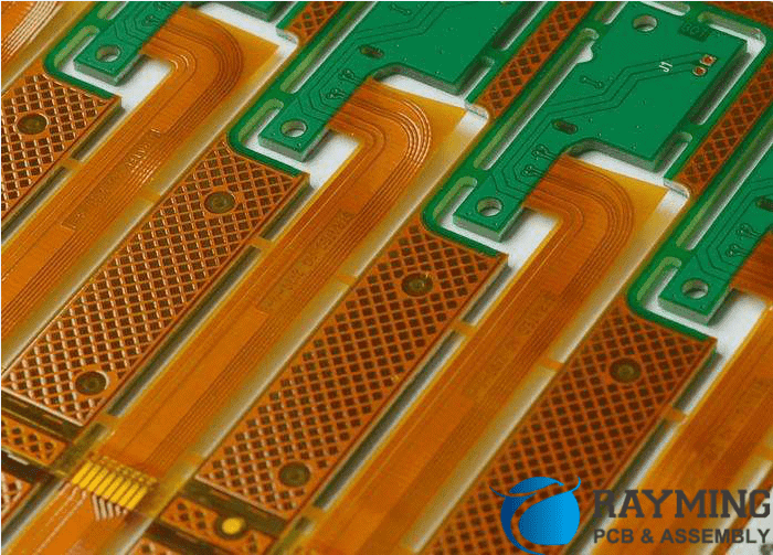
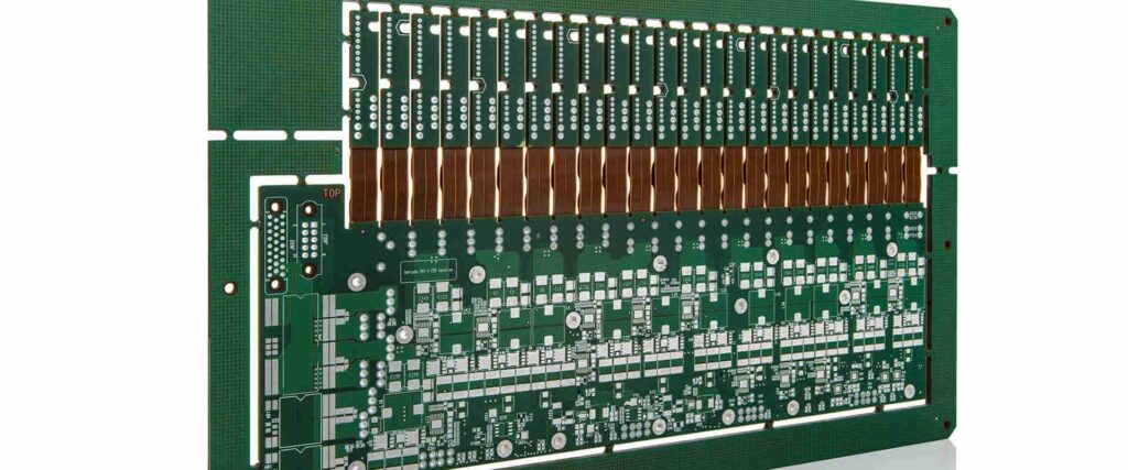
Rigid Flex Construction
There are two main construction methods used to manufacture multilayer rigid flex PCBs:
1. Flex-On-Rigid
With this method, separate rigid and flex layers are manufactured independently. The flexible layers are then laminated onto the rigid board to integrate them together. This allows maximum design flexibility and control over the placement of the flex area.
2. Rigid-Flex-Rigid
Here the rigid and flex layers are laminated together into a single cohesive board. Polyimide films are interleaved between rigid layers to create flexible “hinges” at certain locations along the board. This provides a more seamless integration between rigid and flex but with less control over placement.
Layer Stacking
For a multilayer board, additional polyimide flex layers are stacked up and additional layers of FR-4 are used to build up multiple circuit layers. Stiffeners may be added to provide more stability and prevent flexing in certain areas. Cover layers coat the top and bottom of the stack.
Rigid vs Flex Circuits
Here is a comparison between rigid PCBs and flex circuits:
| Feature | Rigid PCB | Flex Circuit |
|---|---|---|
| Board Materials | FR-4, CEM-1, polyimide | Polyimide films |
| Layer Stacking | Up to 30+ layers | Typically 1-6 layers |
| Thickness | 1.6mm or more | 25μm – 150μm |
| Copper Thickness | 1oz or more | 0.5oz – 2oz typical |
| Minimum Bend Radius | – | 4x thickness typical |
| Assembly | SMT, through-hole | SMT, adhesive mount |
| Key Benefits | – High density<br>- Thick copper for high current | – Dynamic flexing<br>- Light weight |
Quick Turn Rigid Flex PCB Prototypes
Here are some key considerations for getting quality quick turn rigid flex prototypes produced:
Design Optimization
Work closely with your rigid flex PCB manufacturer during the design stage. Their engineering team can help optimize the layout to take full advantage of rigid flex capabilities and avoid common mistakes. Pay special attention to:
- Layer stackup design
- Trace widths and spacing
- Flex layer placement and minimum bend radii
- Component placement for dynamics
- Stiffener requirements
Tolerancing
Use larger tolerances for quick turn prototypes compared to full production. This gives increased margin for error and makes meeting lead times easier for accelerated builds. Critical areas can be held to tighter tolerances when required.
Working with Flex Layers
Factor in that flexible layers require special handling and processing compared to rigid FR-4 layers. For fastest delivery, keep flex layer count to 2-4 layers and avoid multilayer flex areas when possible.
Preparation for Full Production
Even with relaxed tolerances, ensure your quick turn prototypes match your planned full production design as closely as possible. Use the same materials and layer stackup, and order 1-2 test panels built on production equipment. This allows you to qualify manufacturing processes while also evaluating the design.
Documentation
Provide comprehensive design files and documentation up front. For flex boards especially, lack of information can slow down the prototyping process. The more details provided, the faster and less expensive it will be to build boards correctly the first time.
Key Rigid Flex PCB Manufacturing Processes
Rigid flex PCB fabrication combines processes used for rigid boards and flex circuits. Here are some of the key steps:
Imaging and Etching
Rigid layers use standard PCB processes for imaging and etching copper. Flex layers require laser direct imaging (LDI) and specialized etchants formulated for flexible films.
Layer Alignment and Registration
Precision laser alignment systems are used to stack and align layers to tight tolerances across both rigid and flex areas. Cutting systems trim flex layers prior to lamination.
Lamination Cycles
Heat and pressure are applied using specialized lamination presses. The temperature and pressures must be tuned to properly bond flex layers to rigid layers.
Drilling
Extremely precise drilling is needed, especially when drilling through flex areas into rigid layers. Laser drills and special drill bits are used.
Hole Plating
A chemical copper plating process coats the drilled holes. Flexible layers use thin plating for reliability while rigid areas use thicker plating.
Patterning and Etching
Additional copper patterning steps build up circuitry on each layer. Sections are masked and chemically etched to remove excess copper.
Testing and Inspection
100% electrical testing combined with automated optical inspection ensures boards meets performance requirements. Special handling is needed for flex areas.
Benefits of Quick Turn Rigid Flex Prototype PCBs
Here are some of the major benefits of ordering quick turn rigid flex prototypes for your new electronics designs:
- Faster time to market – Quick turn prototypes let you validate your design and start development sooner.
- Improved design performance – Find flaws earlier so they can be corrected prior to release.
- Cost savings – Fixing issues in prototype stage avoids expensive changes later down the line.
- Smooth transition to production – Prototypes match end product for easy transfer to production.
- Risk reduction – Test manufacturing processes and technology risks earlier.
- Verification of specifications – Ensure the design matches all electrical and mechanical requirements.
Quick turn rigid flex PCB prototyping with an experienced manufacturer helps accelerate your development schedule and can get your product to market faster. This allows you to gain a competitive advantage and maximize your return on investment.
Frequently Asked Questions
Here are some common questions about quick turn rigid flex PCB prototyping:
What are typical lead times for quick turn rigid flex prototypes?
For simpler 2-4 layer designs, lead times can be as fast as 24-48 hours. More complex builds with extra pre-production engineering or specialized materials may need 5-10 days.
What design files do I need to provide to the manufacturer?
You’ll need to provide CAD data (Gerber files), board outline drawings, layer stackup info, material callouts, and other documentation that defines the board specifications.
How many prototype boards should I order?
5-10 boards are typically recommended. This allows for some spares in case any are damaged or need to be modified.
Can I make design changes to the boards I receive?
The PCB manufacturer can often accommodate small changes through what’s called an “engineering change order” (ECO). Larger changes may require ordering a new prototype lot.
How are quick turn rigid flex prototypes different than small production runs?
Prototypes use relaxed tolerances, may exclude some tests, and focus on providing a functional sample as fast as possible. Small production runs adhere to full manufacturing and quality standards.
Quick turn rigid flex PCB prototyping can help accelerate product development cycles. Partnering with an experienced manufacturer optimizes the prototyping process so you receive boards that accurately test your design quickly and cost effectively.


Leave a Reply