Introduction to Flexible Printed Circuit Boards
A flexible printed circuit board (PCB), also known as a flex PCB or flex circuit, is a type of PCB that utilizes a flexible plastic substrate instead of a rigid fiberglass material. Flex PCBs can be bent, folded, twisted, and contorted to fit into tight spaces and dynamically flexing applications.
Some key advantages of flexible PCBs include:
- Ability to fit into small, complex spaces and move dynamically
- Lightweight and thin profile
- Good electrical performance with controlled impedance
- Cost-effective for high volume production
- Reliable and durable if properly designed
Flex PCBs are commonly used in the following applications:
- Consumer electronics – Cell phones, laptops, VR headsets
- Automotive & transportation – Sensors, control panels
- Medical devices – Hearing aids, imaging equipment
- Industrial automation – Robotics, motion control
- Aerospace and defense – Avionics, radars
What is Pyralux Flex PCB Material?

Pyralux is a brand of flexible circuit materials manufactured by DuPont for use in flex PCB designs. The Pyralux line includes a variety of different flexible dielectric substrates and copper-clad laminates to choose from.
Some of the key benefits of Pyralux flex materials include:
- Good dielectric strength and thermal performance
- Wide range of material thicknesses available
- Can support high layer counts and fine lines/spaces
- RoHS compliant and halogen-free options
- Some variants are UL recognized and CTI approved
Pyralux materials are designed for excellent processing through standard PCB fabrication methods while maintaining flexibility and reliability. They are engineered to withstand dynamic flexing, twisting, folding without damage.
Some of the most popular Pyralux flexible material options include:
Pyralux AP
- All-polyimide dielectric layers
- Excellent thermal performance and cut-through resistance
- Thicknesses from 25μm to 150μm
- Popular for high reliability applications
Pyralux LF
- Modified acrylic adhesive dielectric
- More economical option
- Thicknesses from 25μm to 100μm
- Ideal for consumer electronics
Pyralux FR
- Polyimide dielectric with flame retardant
- Meets UL94 V-0 flame rating
- Thicknesses from 50μm to 100μm
- Used when flammability standards must be met
Pyralux TK
- Modified polyimide dielectric with adhesive
- Composite construction
- Thicknesses from 50μm to 152μm
- Combines flexibility with thermal performance
In addition to the base dielectric layers, Pyralux copper-clad laminates are also available in different copper weights, with options ranging from thin 1⁄4 oz copper up to 2 oz thick copper. The copper foil provides the conductive traces for transmitting signals and power.
Design Considerations for Pyralux Flex PCBs
When designing a flex PCB using Pyralux materials, there are some important considerations to factor in to ensure reliability and performance.
Layer Stackup
The layer stackup defines the layer construction of the flex PCB. For Pyralux boards, common stackups include:
- Single-sided – Copper on one side only
- Double-sided – Copper on both sides
- Multilayer – Multiple dielectric layers with copper traces in between
Multilayer stackups allow for higher circuit density and more complex routing. Pyralux materials can support high layer count constructions up to 30 layers or more.
Dielectric Material Selection
Choosing the right Pyralux dielectric material is key based on the application requirements, cost targets, and circuit performance needs. Key factors in dielectric selection include:
- Thickness – Thinner dielectrics enable smaller bend radii
- Flexibility – How much bending is required? Acrylic or polyimide?
- Thermal performance – Polyimide offers superior thermal properties
- Adhesion – Adhesiveless or adhesive-based dielectrics?
- Flammability rating – Standard or flame retardant materials?
Copper Weight
The selected copper foil thickness impacts flexibility, current carrying capacity, and signal integrity. Thinner copper enables tighter bend radii, while thicker copper handles more current. 1⁄2 oz and 1 oz copper weights are commonly used.
Bend Radius
A minimum bend radius must be maintained to prevent damage to the flex PCB. The bend radius is based on the material stackup, copper weight, and other factors. Tighter bend radii are possible with thinner, more flexible materials.
Routing and Trace Width/Spacing
Finer trace widths and smaller spaces between traces are possible with thinner Pyralux materials and copper weights. Typical trace widths range from 10μm to 150μm.
Stiffeners and Solder Mask
Strategically placed stiffeners may be required to reinforce areas subject to stresses, or to mount components. Solder mask can also help distribute flexing stresses.
Testing and Certification
Pyralux flex materials support qualifications such as UL recognition for flammability ratings, contamination testing like IPC-CC-830, and other industry testing procedures.
Pyralux Flex PCB Fabrication Processes

Pyralux flex PCBs utilize the same standard PCB processes used in rigid PCB fabrication. This includes the following steps:
Lamination
Multiple layers of Pyralux copper clad laminates are stacked and laminated together under heat and pressure to bond the layers into a unified circuit board. Adhesive or adhesiveless laminations are used depending on the material.
Drilling
Microvias and through holes are mechanically drilled into the laminated board to form vertical interconnects between layers. Excellent positional accuracy is required.
Metallization
The drilled holes are metallized via copper electroplating to form a conductive connection between layers.
Photolithography
A photoresist is applied on the copper layers. The circuit patterns are then exposed to UV light through a photomask.
Etching
The unexposed copper is etched away, leaving only the desired copper circuit pattern behind.
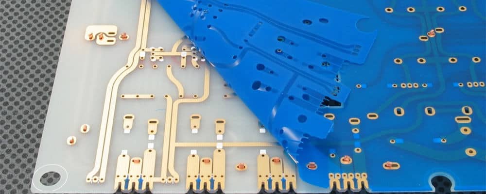
Solder Mask
A solder mask coating is applied and imaged to selectively cover parts of the copper traces for protection.
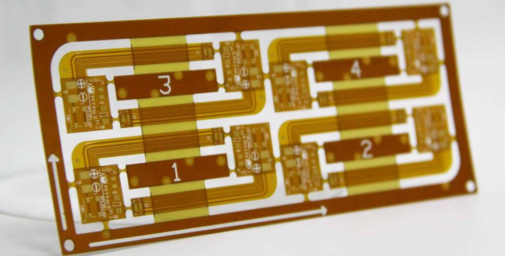
Routing and Scoring
Mechanical routing and scoring operations are performed to singulate individual boards or create flexing points.
Final Testing
100% electrical testing and inspection verifies the completed flex PCBs meet specifications and quality requirements.
Precision process control at each step ensures reliability and performance of the completed Pyralux flex circuits.
Key Applications of Pyralux Flexible PCBs
Thanks to their flexibility and durability, Pyralux PCBs are utilized in a wide range of demanding application environments.
Aerospace and Defense
Pyralux polyimide-based materials are ideal for aerospace and defense systems requiring ruggedness along with lightweight and compact form factors. Common uses include avionics systems, radar antennas, missile guidance systems, and other airborne electronics.
Medical Electronics
In medical devices like hearing aids, imaging systems, and surgical equipment, Pyralux flex materials withstand continuous dynamic flexing and prevent failures. Biocompatible coverlay materials are also available.
Consumer Wearables
For wearable devices like smart watches and fitness trackers, thin and flexible Pyralux circuits can conform to the user’s wrist or body comfortably. The materials withstand twisting and fatigue reliably.
Automotive Applications
Pyralux materials meet automotive industry flammability ratings and environmental requirements. Flex circuits are used for under-hood electronics, driver displays, sensors, and other demanding under-car applications.
Industrial Automation
Withstanding vibration and repeated motion is crucial for industrial robots and automated machinery. Pyralux flex circuits provide reliable interconnections despite continuous dynamic movement.
Thanks to their unique properties and advantages, Pyralux materials will continue enabling the latest flexible PCB innovations across these industries and more.
Frequently Asked Questions
What are the main advantages of Pyralux flex PCBs?
Some of the main benefits of Pyralux flexible PCBs include excellent flex durability, a wide range of material options, good thermal and electrical performance, UL rating capabilities, and suitability for high volume manufacturing.
How flexible can Pyralux PCBs be?
With proper design, Pyralux flex PCBs can be folded completely in half, twisted 90 degrees or more, or dynamically flexed hundreds of thousands of times without failure. The flexibility depends on factors like material thickness and minimum bend radii.
Can components be mounted on Pyralux flexible circuits?
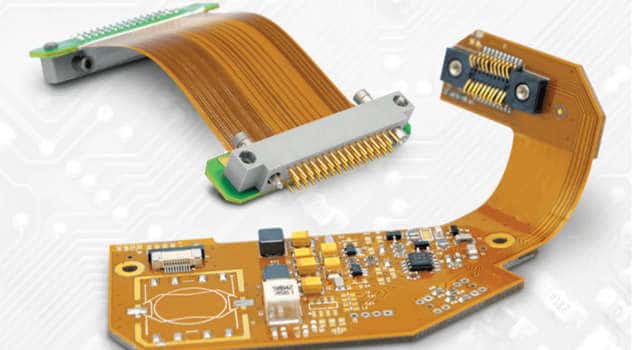
Yes, components can be surface mounted onto Pyralux flex PCBs. Care must be taken in the component selection, attachment process, and managing stresses to ensure reliability. Stiffeners may be used to reinforce component mounting areas.
What types of connectors work well with Pyralux PCBs?
Various connectors are suitable for Pyralux flex PCBs, such as compressible “pogo” connectors, anisotropic conductive film (ACF) connectors, or zero-insertion force (ZIF) connectors. The connector style depends on the application.
Are Pyralux flex materials compatible with high-speed signals?
Yes, Pyralux materials support controlled impedance flex PCBs suitable for high-speed signals exceeding multi-Gbps data rates. With proper stackup design, Pyralux can provide excellent signal integrity even with 90 degree bends.
How are Pyralux flex PCBs tested and qualified?
Pyralux circuits can be subjected to a wide array of tests including flammability testing, bend cycle life testing, vibration testing, humidity/temperature cycling, solder float testing, electric field/breakdown testing, and other relevant tests per application standards.


Leave a Reply