What is the PICKit 3?
The PICKit 3 is a development tool designed by Microchip Technology for programming and debugging PIC microcontrollers. It offers a wide range of features, including:
- In-Circuit Debugging (ICD)
- In-Circuit Serial Programming (ICSP)
- Real-time execution and debugging
- Support for a wide range of PIC microcontrollers
- USB connectivity for easy integration with a computer
PICKit 3 Pinout Overview
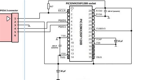
The PICKit 3 features a 6-pin header that provides access to the necessary signals for programming and debugging PIC microcontrollers. Here’s an overview of the PICKit 3 pinout:
| Pin | Name | Description |
|---|---|---|
| 1 | VPP | Programming voltage (12V) |
| 2 | VDD | Target device supply voltage (2-5V) |
| 3 | GND | Ground |
| 4 | PGD | Programming data (ICSPDAT) |
| 5 | PGC | Programming clock (ICSPCLK) |
| 6 | PGM | Low Voltage Programming (LVP) enable |
1. VPP (Programming Voltage)
The VPP pin supplies the programming voltage required for certain PIC microcontrollers. This voltage is typically 12V and is used during the programming process to erase and write the device’s flash memory.
2. VDD (Target Device Supply Voltage)
The VDD pin provides power to the target PIC microcontroller during programming and debugging. The PICKit 3 can supply a voltage between 2V and 5V, depending on the requirements of the target device.
3. GND (Ground)
The GND pin is the common ground reference for the PICKit 3 and the target device. It ensures a stable and reliable connection between the two.
4. PGD (Programming Data)
The PGD pin, also known as ICSPDAT, is used for bidirectional data communication between the PICKit 3 and the target PIC microcontroller during programming and debugging.
5. PGC (Programming Clock)
The PGC pin, also known as ICSPCLK, provides the clock signal necessary for synchronizing the communication between the PICKit 3 and the target device during programming and debugging.
6. PGM (Low Voltage Programming Enable)
The PGM pin is used to enable Low Voltage Programming (LVP) mode on compatible PIC microcontrollers. When connected to ground, LVP mode is activated, allowing programming and debugging at lower voltages.

Connecting the PICKit 3 to a Target Device
To connect the PICKit 3 to a target PIC microcontroller, follow these steps:
- Ensure that the target device is powered off.
- Connect the PICKit 3 to the target device using the appropriate pinout. Make sure that the VPP, VDD, GND, PGD, and PGC pins are correctly aligned.
- If your target device supports Low Voltage Programming (LVP), connect the PGM pin to ground.
- Power on the target device.
- Connect the PICKit 3 to your computer using a USB cable.

Using the PICKit 3 with MPLAB X IDE
The PICKit 3 is fully compatible with Microchip’s MPLAB X Integrated Development Environment (IDE). MPLAB X IDE provides a user-friendly interface for programming and debugging PIC microcontrollers using the PICKit 3. Here’s how to use the PICKit 3 with MPLAB X IDE:
- Install MPLAB X IDE on your computer.
- Launch MPLAB X IDE and create a new project or open an existing one.
- Configure the project settings to use the PICKit 3 as the programmer/debugger tool.
- Build your project to generate the necessary hex file.
- Connect the PICKit 3 to your target device and computer as described in the previous section.
- Use the programming and debugging features of MPLAB X IDE to load your code onto the target device and debug it in real-time.

PICKit 3 Pinout Diagrams
To help you better understand the PICKit 3 pinout, here are some visual representations:
Standard PICKit 3 Pinout
     ___________
    |           |
    | 1 2 3 4 5 |
     \_________/
        |||||
        |||||
        |||||
        |||||
        |||||
        12345
PICKit 3 Pinout with LVP Enabled
     ___________
    |           |
    | 1 2 3 4 5 |
     \_________/
        |||||
        |||||
        |||||
        |||||
        |||||
        12345
         |
         |
         |
        GND
Troubleshooting Common PICKit 3 Issues
If you encounter problems while using the PICKit 3, here are some common issues and their solutions:
-
PICKit 3 not detected by MPLAB X IDE: Ensure that the PICKit 3 is properly connected to your computer and that the USB drivers are installed correctly. If the issue persists, try using a different USB port or cable.
-
Target device not responding: Double-check that the PICKit 3 pinout is correctly connected to the target device. Verify that the target device is powered on and that the correct programming voltage is being supplied.
-
Programming failures: Make sure that the hex file generated by MPLAB X IDE is compatible with your target device. Check for any errors in your code that may prevent successful programming.
-
Debugging issues: Ensure that the debug settings in MPLAB X IDE are configured correctly for your target device. Verify that the PICKit 3 is properly connected and that the target device is in a debuggable state.
If you continue to experience issues, consult the PICKit 3 documentation or seek assistance from the Microchip support community.
Frequently Asked Questions (FAQ)
-
Q: Can the PICKit 3 be used with non-Microchip microcontrollers?
A: No, the PICKit 3 is designed specifically for programming and debugging Microchip PIC microcontrollers and is not compatible with other manufacturers’ devices. -
Q: Is the PICKit 3 compatible with all PIC microcontrollers?
A: The PICKit 3 supports a wide range of PIC microcontrollers, but not all of them. Check the Microchip website or documentation for a list of compatible devices. -
Q: Can I use the PICKit 3 without MPLAB X IDE?
A: While MPLAB X IDE provides a user-friendly interface for the PICKit 3, it is possible to use the PICKit 3 with other software tools or even custom programming solutions. However, this requires a deeper understanding of the PICKit 3 communication protocol and may not be suitable for beginners. -
Q: What is the maximum voltage that the PICKit 3 can supply to the target device?
A: The PICKit 3 can supply a voltage between 2V and 5V to the target device through the VDD pin. The exact voltage depends on the requirements of the specific PIC microcontroller being used. -
Q: Is the PICKit 3 open-source?
A: No, the PICKit 3 is a proprietary tool developed by Microchip Technology. While some aspects of its communication protocol are documented, the complete design and firmware are not open-source.
Conclusion
The PICKit 3 is a versatile and powerful tool for programming and debugging PIC microcontrollers. By understanding the PICKit 3 pinout and its features, you can effectively use this tool to develop and troubleshoot your PIC-based projects. Whether you’re a beginner or an experienced developer, the PICKit 3 is an invaluable asset in your toolbox.
Remember to always refer to the official Microchip documentation and resources for the most up-to-date information on the PICKit 3 and its supported devices. Happy programming and debugging with your PICKit 3!


Leave a Reply