What is a Peak Detector?
A peak detector, also known as a peak hold or envelope detector, is an electronic circuit that captures and retains the highest (peak) value of an input signal over a period of time. It essentially “remembers” the maximum amplitude of the signal, even after the signal level decreases. This is particularly useful when you need to measure or record the peak value of a rapidly changing or intermittent signal.
The basic principle behind a peak detector is relatively simple. The circuit consists of a diode, a capacitor, and a resistor. When the input signal rises above the voltage stored in the capacitor, the diode conducts and charges the capacitor to the new peak value. When the input signal falls below the capacitor voltage, the diode becomes reverse-biased, preventing the capacitor from discharging back through the input. The resistor slowly bleeds off the charge in the capacitor, allowing the circuit to reset and detect new peaks.
Applications of Peak Detectors
Peak detectors find applications in a wide range of electronic systems and devices. Some common use cases include:
-
Audio Signal Processing: Peak detectors are used in audio compressors, limiters, and automatic gain control (AGC) circuits to detect and control the peak levels of audio signals, preventing clipping and distortion.
-
Instrumentation: In measurement and instrumentation systems, peak detectors are employed to capture and hold the maximum value of a sensor output, such as temperature, pressure, or vibration sensors.
-
Data Logging: Peak detectors can be used in data acquisition systems to record the maximum values of various parameters over time, enabling efficient data storage and analysis.
-
Pulse Detection: In digital communication systems, peak detectors are used to detect the presence and amplitude of pulse signals, facilitating signal demodulation and decoding.
-
Envelope Detection: Peak detectors form the core of envelope detectors, which extract the amplitude envelope of a modulated signal, such as in AM (amplitude modulation) radio receivers.

Building a Simple Peak Detector Circuit
Now that we understand the basics of peak detectors and their applications, let’s dive into building a simple peak detector circuit using readily available components.
Components Required
To build a basic peak detector circuit, you’ll need the following components:
| Component | Quantity | Description |
|---|---|---|
| Schottky Diode | 1 | 1N5817 or similar |
| Capacitor | 1 | 1 µF, ceramic or film |
| Resistor | 1 | 1 MΩ, 1/4 W |
| Op-amp | 1 | LM358 or similar |
| Breadboard | 1 | For prototyping |
| Jumper Wires | As needed | For connections |
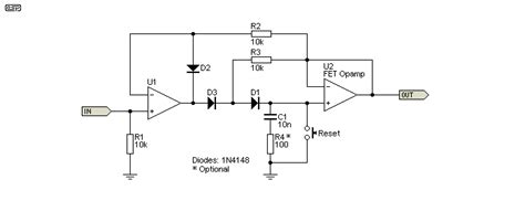
Circuit Diagram
Here’s a simple schematic diagram of the peak detector circuit:
        +---------+
  IN ---| Diode   |--- OUT
        |         |
        | Resistor|
        |         |
  GND --|Capacitor|-- GND
        +---------+
Step-by-Step Instructions
-
Set up the breadboard: Place the op-amp (LM358) on the breadboard, ensuring that it straddles the center gap. Connect the positive supply voltage (V+) to the op-amp’s pin 8 and the negative supply voltage (V-) or ground to pin 4.
-
Connect the input: Connect the input signal to the non-inverting input (pin 3) of the op-amp through the Schottky diode (1N5817). The anode of the diode should be connected to the input signal, and the cathode should be connected to pin 3.
-
Add the capacitor: Connect the 1 µF capacitor between the op-amp’s output (pin 1) and the inverting input (pin 2). This capacitor stores the peak voltage.
-
Add the resistor: Connect the 1 MΩ resistor between the inverting input (pin 2) and ground. This resistor provides a discharge path for the capacitor, allowing the circuit to reset and detect new peaks.
-
Connect the output: The peak-detected output signal is available at the op-amp’s output (pin 1). Connect this to your desired load or measurement device.
Circuit Operation
When an input signal is applied to the peak detector circuit, the op-amp operates as a voltage follower, driving its output to match the input voltage. If the input voltage rises above the voltage stored in the capacitor, the diode conducts, allowing the capacitor to charge up to the new peak value. When the input voltage falls below the capacitor voltage, the diode becomes reverse-biased, preventing the capacitor from discharging back through the input.
The resistor connected between the inverting input and ground provides a slow discharge path for the capacitor. The discharge time constant is determined by the product of the capacitor value and the resistor value (τ = RC). By adjusting these component values, you can control how long the peak detector holds the peak value before resetting.
It’s important to note that the Schottky diode is used in this circuit due to its low forward voltage drop and fast switching characteristics. This ensures accurate tracking of the input signal and minimizes errors in the peak detection process.

Advanced Peak Detector Techniques
While the basic peak detector circuit described above is sufficient for many applications, there are several advanced techniques you can employ to enhance its performance and adapt it to specific requirements.
Precision Peak Detectors
For high-precision applications, you can improve the accuracy of the peak detector by using a precision op-amp with low input offset voltage and low input bias current. Additionally, using a low-leakage capacitor, such as a polypropylene or polyester film capacitor, can minimize droop and maintain the peak value for longer periods.
Resettable Peak Detectors
In some cases, you may want to manually reset the peak detector to start a new measurement cycle. To achieve this, you can add a reset switch or a transistor-based reset circuit that discharges the capacitor when triggered. This allows you to control the timing of the peak detection and synchronize it with other system events.
Programmable Peak Detectors
For advanced applications that require dynamic control over the peak detection parameters, you can implement a programmable peak detector using a microcontroller or a digital-to-analog converter (DAC). By digitally controlling the discharge resistor or the reference voltage, you can adjust the sensitivity, threshold, and reset time of the peak detector on the fly.
Dual-Polarity Peak Detectors
In some situations, you may need to detect both positive and negative peaks of an input signal. To achieve this, you can use two peak detector circuits in parallel, with one detecting the positive peaks and the other detecting the negative peaks. The outputs of the two detectors can then be combined or processed separately, depending on the application requirements.

Troubleshooting and Tips
When building and using peak detector circuits, keep the following troubleshooting tips and guidelines in mind:
-
Input Signal Range: Ensure that the input signal amplitude is within the acceptable range of the op-amp and the diode. Exceeding the maximum ratings can damage the components and lead to inaccurate results.
-
Discharge Time Constant: Choose the capacitor and resistor values carefully to set the desired discharge time constant. A longer time constant will hold the peak value for a longer duration but may result in slower response to new peaks.
-
Diode Selection: Use a diode with low forward voltage drop and fast switching speed, such as a Schottky diode, to minimize errors and ensure accurate peak detection.
-
Op-Amp Selection: Choose an op-amp with appropriate specifications for your application, considering factors such as input offset voltage, input bias current, slew rate, and bandwidth.
-
Power Supply Decoupling: Ensure proper power supply decoupling by placing bypass capacitors close to the op-amp’s supply pins to reduce noise and improve stability.
-
PCB Layout: When designing a printed circuit board (PCB) for the peak detector, pay attention to proper grounding, signal routing, and component placement to minimize parasitic effects and interference.
Frequently Asked Questions (FAQ)
-
What is the purpose of the diode in a peak detector circuit?
The diode in a peak detector circuit allows the capacitor to charge up to the peak value of the input signal when the input voltage rises above the capacitor voltage. When the input voltage falls below the capacitor voltage, the diode becomes reverse-biased, preventing the capacitor from discharging back through the input. -
Can I use a regular diode instead of a Schottky diode in the peak detector circuit?
While you can use a regular diode, such as a 1N4148, in the peak detector circuit, a Schottky diode is preferred due to its low forward voltage drop and fast switching characteristics. This ensures accurate tracking of the input signal and minimizes errors in the peak detection process. -
How do I set the discharge time constant of the peak detector?
The discharge time constant of the peak detector is determined by the product of the capacitor value and the resistor value connected between the inverting input and ground (τ = RC). By adjusting these component values, you can control how long the peak detector holds the peak value before resetting. -
What happens if the input signal exceeds the maximum ratings of the op-amp or diode?
If the input signal amplitude exceeds the maximum ratings of the op-amp or diode, it can damage the components and lead to inaccurate results. Always ensure that the input signal is within the acceptable range specified in the component datasheets. -
Can I use a peak detector for AC signals?
Yes, you can use a peak detector for AC signals. However, you may need to add an input coupling capacitor to remove any DC offset and ensure that the AC signal is properly centered around the diode’s forward voltage drop. Additionally, you may need to adjust the discharge time constant to match the frequency of the AC signal.
Conclusion
Peak detector circuits are versatile and essential tools in the world of electronics, finding applications in audio processing, instrumentation, data logging, and more. By understanding the basic principles and components of a peak detector, you can easily build one using simple, readily available parts.
Throughout this article, we’ve covered the fundamentals of peak detectors, their applications, and a step-by-step guide to building a simple peak detector circuit. We’ve also explored advanced techniques for enhancing peak detector performance and adapting them to specific requirements.
By following the guidelines and troubleshooting tips provided, you’ll be well-equipped to design, build, and implement peak detector circuits in your own projects. Whether you’re a hobbyist, a student, or a professional engineer, mastering the art of peak detection will undoubtedly expand your electronics toolkit and open up new possibilities in signal processing and measurement.
So, grab your components, fire up your soldering iron, and start experimenting with peak detectors today! With a little practice and patience, you’ll be capturing and holding those elusive signal peaks in no time.


Leave a Reply