What is PCB Thermal Conductivity?
PCB (printed circuit board) thermal conductivity refers to the ability of a PCB material to conduct heat. It is a measure of how efficiently heat transfers through the board from hot components to cooler areas or a heatsink. Thermal conductivity is expressed in Watts per meter-Kelvin (W/mK).
Higher thermal conductivity allows heat to dissipate more rapidly and evenly across the PCB. This helps prevent hot spots from forming around power-hungry components like processors, FPGAs, graphics chips, etc. Low thermal conductivity can lead to components overheating and failing prematurely.
Typical PCB base materials like FR-4 have relatively low thermal conductivity (0.25-0.4 W/mK). However, there are many thermally enhanced PCB Laminates and fillers available that provide higher conductivity for improved heat transfer.
Importance of PCB Thermal Management
Proper thermal management is critical in electronics design and manufacturing for several reasons:
- Prevents overheating and component failure
- Improves reliability and product lifespan
- Enables higher power density
- Allows for smaller form factors
- Meets safety and regulatory requirements
As electronic systems trend towards higher speeds, smaller sizes, and greater functionality, power density increases along with waste heat generation. Accumulated heat must be effectively removed from sensitive semiconductor junctions. Otherwise, high temperatures will degrade performance, cause malfunctions, and shorten product life.
Military, aerospace, and medical applications have particularly stringent reliability requirements. Excess heat is a common culprit behind field failures and product returns. Effective thermal management using high conductivity materials is essential.
Consumer gadgets like smartphones and laptops also benefit from thermal enhancements. Better heat spreading allows for thinner, sleeker designs without sacrificing performance. Nobody wants their device to become uncomfortably hot during use.

Factors Affecting PCB Thermal Conductivity
Several key factors influence the thermal conductivity of a PCB:
Base Material
The core and prepreg materials used to construct the board are the biggest determinants of overall thermal conductivity. Standard FR-4 epoxy-glass is an electrical insulator with conductivity around 0.25-0.4 W/mK.
Thermally enhanced FR-4 may include fillers like ceramic or boron nitride to boost conductivity to the 0.5-1.0 W/mK range. Polyimide and PTFE laminates tend to be somewhat higher than basic FR-4.
Some specialty laminates use metal cores for greatly increased conductivity:
| Material | Thermal Conductivity (W/mK) |
|---|---|
| Aluminum | 120-237 |
| Copper | 385-401 |
| Invar | 10-20 |
Metal core boards are commonly used in high-power LED lighting. The metal helps quickly spread heat from the LED junctions to an external heat sink.
Copper Thickness
The thickness of the copper traces and planes also affects PCB thermal conductivity. Thicker copper provides a larger cross-sectional area for heat flow. 1 oz. copper foil (35 μm) is standard, but 2-10 oz. weights are also available for high-current and thermal applications.
Heavy copper is often used in power electronics PCBs to accommodate the required current capacity. The additional copper thickness also helps spread heat more evenly.
Thermal Vias
Thermal vias are small plated holes that provide a conductive path for heat to flow through the board. They are typically placed in an array pattern beneath high-power components. The vias transfer heat through the PCB to internal ground planes or to heatsinks on the opposite side.
Via size, pitch, and plating thickness all influence the effective thermal conductivity. More vias, larger diameters, and thicker plating improve heat transfer.
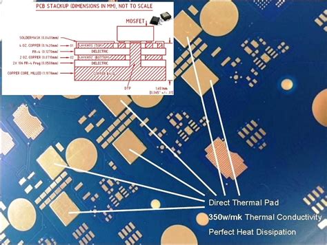
PCB Stackup
The layer arrangement in a multi-layer PCB can be optimized for thermal performance. Placing ground planes close to hot components and traces helps spread heat laterally. Thick internal planes also conduct heat through the board to other copper features or thermal vias.
Boards may be constructed with an asymmetric stackup that concentrates copper on one side. This improves thermal conductivity in that direction to a heatsink.

Measuring PCB Thermal Conductivity
Accurate thermal conductivity data is important for modeling and simulation. Design engineers need this information to evaluate materials and make decisions. There are several methods for measuring PCB thermal conductivity:
ASTM D5470
ASTM D5470 is a standard test method that sandwiches a thin sample between two metal blocks with known temperatures. Heat flows through the sample from the hot block to the cold one. The temperature gradient and heat flux are used to calculate thermal conductivity and thermal resistance.
This method works well for homogeneous materials, but can be inaccurate for multi-layer PCBs with anisotropic properties. The ASTM D5470 fixture also tends to compress the sample, which may not match real-world conditions.
Guarded Heat Flow Meter
A guarded heat flow meter controls temperature on either side of a sample using special guard heaters. The amount of electrical power required to maintain steady-state conditions is used to determine thermal conductivity.
Heat flow meter setups are more complex than ASTM D5470, but they provide accurate results for a variety of sample types and temperatures. Careful calibration is important.
Laser Flash
The laser flash method rapidly heats one side of a sample with a pulse of light energy. An infrared sensor measures the temperature rise on the opposite face over time. Thermal diffusivity is calculated from the temperature vs. time curve. Thermal conductivity can then be derived if density and specific heat capacity are known.
Laser flash works well for multi-layer boards because the energy pulse penetrates through the sample. The test is fast and non-destructive. However, translucent or reflective materials may require special sample preparation.

Designing PCBs for Optimal Thermal Performance
When designing a PCB, there are several best practices to enhance thermal conductivity and heat transfer:
Use Thermally Enhanced Materials
If your application has significant power dissipation or high ambient temperatures, consider using a thermally enhanced base material. Ceramic-filled or metal core substrates provide much better conductivity than standard FR-4.
Increase Copper Weight
Specify thicker copper foil for high-current traces, planes, and heatsinking areas. 2 oz. copper can carry about 40% more current than 1 oz. for the same temperature rise. The added cross-section also lowers thermal resistance.
Optimize Via Layout
Use arrays of thermal vias to conduct heat away from hot components. Stagger the vias for maximum effectiveness. Simulate your layout to determine the optimal via size, pitch, and plating requirements. Through-hole vias provide the best heat transfer, but blind and buried vias are also helpful.
Use Solid Copper Pours
Flood unused areas of the board with solid copper pours connected to ground. This increases the total volume of copper available for heat spreading and lowers thermal resistance. Pours on multiple layers are even better.
Separate Hot and Cold Components
Place high-power components like processors and FPGAs away from temperature-sensitive devices. Provide adequate space for heat to dissipate. Cluster hot components together near heatsinks or board edges for improved convective cooling.
Optimize Stack-up
Arrange your stack-up to provide the most direct thermal path from heat sources to heatsinks. Place ground and power planes close to hot components. Use thicker internal planes and consider metal-backed substrates for the best performance.
FAQ
Q1: What is a good PCB thermal conductivity for high-power applications?
A1: For high-power applications, look for thermally enhanced PCB materials with conductivity of at least 1.0 W/mK. Some ceramic-filled and metal core substrates can provide 2-10 W/mK or more. Standard FR-4 is usually insufficient at 0.25-0.4 W/mK.
Q2: Do I need thermal vias for every component?
A2: Not every component requires thermal vias. Focus on high-power devices like processors, FPGAs, MOSFETs, and voltage regulators that generate significant heat. Low-power components like resistors and small ICs can usually be cooled adequately through the board material and copper traces.
Q3: What is the best way to measure PCB thermal conductivity?
A3: The best measurement method depends on your sample type and accuracy requirements. ASTM D5470 is a quick and simple method for reference-grade materials. Guarded heat flow meters provide good accuracy for non-homogeneous samples. Laser flash is fast and non-destructive for multi-layer boards. Always follow proper calibration and sample preparation procedures.
Q4: How much copper is needed for good thermal performance?
A4: For high-current and thermal applications, 2 oz. copper (70 μm) or thicker is recommended. This provides about 40% more current carrying capacity and thermal conductivity than standard 1 oz. foil. Even thicker copper (3-10 oz.) may be used for extreme cases. Increasing copper thickness provides diminishing returns, so simulate your design to find the optimal weight.
Q5: Can I use thermal interface materials (TIMs) to improve PCB cooling?
A5: Yes, TIMs like thermal greases, pads, and adhesives can improve heat transfer between PCBs and heatsinks. They fill in microscopic air gaps and irregularities to increase contact area and thermal conductivity. Select a TIM with the appropriate thermal properties, bond line thickness, and dispensing method for your application. Proper surface preparation and application technique are critical for optimal performance.
Conclusion
Thermal conductivity is a critical parameter for PCB materials and designs. As electronic systems become more compact and power-dense, effective thermal management is essential for reliability and performance. Designers must carefully select PCB materials, copper weights, via layouts, and stack-ups to provide adequate cooling.
Thermally enhanced substrates, high copper weights, and optimized via arrays are key tools for improving heat transfer. Designers should also consider component placement, copper pours, and interface materials to further optimize thermal performance.
Accurate thermal conductivity measurements are important for modeling and simulation. ASTM D5470, guarded heat flow meters, and laser flash techniques can provide reliable data for different sample types.
By understanding the factors affecting PCB thermal conductivity and following best design practices, engineers can develop products that meet demanding thermal requirements. Proper thermal management helps ensure reliable operation, long lifetimes, and satisfied customers.


Leave a Reply