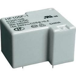
What is a PCB Relay?
A PCB relay, or printed circuit board relay, is a compact electromechanical switching device mounted directly onto a PCB. It allows a low-power signal to control a high-power circuit, providing isolation between control and load circuits. PCB relays come in various types, sizes, and ratings to suit different applications.
Key Features of PCB Relays
- Small size for space-constrained PCB designs
- Wide range of coil voltages (3V to 24V DC typical)
- Switching capacities from a few amps to 10+A
- Available in 1 Form A (SPST-NO), 1 Form B (SPST-NC), 1 Form C (SPDT), 2 Form A, 2 Form C and other contact arrangements
- Sealed and washable versions for harsh environments
- Low coil power consumption
- Fast switching times
- Long mechanical life (10-100 million operations)
- Dielectric strength of several kilovolts between coil and contacts
- RoHS compliant and Pb-free
How a PCB Relay Works
A relay has two main parts:
- Coil – An electromagnet that actuates the switching mechanism when energized.
- Contacts – The conductive elements that open or close to switch the load circuit.
When a control voltage is applied to the coil, it generates a magnetic field that attracts a ferromagnetic armature. The armature movement actuates the contacts, changing their state from open to closed or vice versa. When coil voltage is removed, a spring returns the armature and contacts to their original positions.
Relay Operation Sequence:
- Coil is energized by the control signal
- Coil current generates magnetic flux
- Magnetic force overcomes spring tension and pulls armature
- Armature movement actuates moving contact
- Moving contact touches or separates from stationary contacts
- Coil is de-energized
- Spring returns armature and contacts to initial positions

Types of PCB Relays
1. General Purpose Relays
General purpose PCB relays are the most common type, suitable for a wide range of switching applications. They typically have:
- SPDT (Form C) contact arrangement
- 5A to 10A switching capacity at 250VAC
- Coil voltages of 3V, 5V, 12V, 24V DC
- Dimensions around 20mm x 10mm x 15mm
- Power, signal, and control circuit switching
- Telecom, security, industrial and consumer use
2. Reed Relays
Reed relays use hermetically sealed reed switches actuated by an external electromagnet. Characteristics include:
- Very small size (10mm x 5mm x 5mm)
- Switching up to 0.5A at 100VDC
- Coil voltages of 3V, 5V, 12V DC
- Low coil power consumption (typ. 20-100 mW)
- Fast operate and release times (under 1ms)
- Billions of operations possible
- Ideal for low-level, high-speed signal switching
3. High Voltage Relays
High voltage PCB relays switch loads above 250VAC. Key features:
- SPST or SPDT contacts rated up to 1000VAC
- Switching currents around 1-5A
- High dielectric strength coil-contact isolation
- Dimensions approx. 30mm x 15mm x 20mm
- Applications in power supplies, test equipment, and high voltage circuit control
4. Latching Relays
Latching PCB relays maintain their contact state without continuous coil energization. They use a permanent magnet or mechanical latch.
- Reduced coil power consumption
- Set and reset coils for state changes
- Larger size than non-latching relays
- Suitable for battery-powered devices and energy-sensitive designs
5. Solid State Relays (SSRs)
SSRs use semiconductor switching elements like thyristors, triacs or MOSFETs instead of mechanical contacts.
- No moving parts, unlimited electric life
- Fast switching times (microseconds to milliseconds)
- Silent operation
- Higher cost than electromechanical relays
- Load ratings up to 5A
- Used for frequent switching and high inrush loads

PCB Relay Specifications
When selecting a PCB relay, consider the following key specifications:
| Parameter | Description | Typical Value |
|---|---|---|
| Rated Coil Voltage | Nominal coil energizing voltage | 3, 5, 12, 24 VDC |
| Coil Power Consumption | Power required by coil at rated voltage | 100 to 800 mW |
| Rated Load Voltage | Maximum switching voltage (AC or DC) | 250 VAC, 30 VDC |
| Rated Load Current | Maximum switching current | 2 to 10 A |
| Contact Arrangement | Number and type of contacts (Form A, B, C, etc.) | SPDT (1 Form C) |
| Contact Resistance | Resistance of closed contacts | 50 to 100 mΩ |
| Operate Time | Time from coil energization to contact closure | 2 to 15 ms |
| Release Time | Time from coil de-energization to contact opening | 1 to 10 ms |
| Insulation Resistance | Resistance between open contacts, and contacts to coil (at 500VDC) | >1000 MΩ |
| Dielectric Strength | AC voltage withstand between open contacts, and contacts to coil | 1000 to 5000 VAC |
| Mechanical Life | Number of possible switching cycles | 10 to 100 million |
| Electrical Life | Switching cycles under rated load | 100,000 to 1 million |
Other important parameters include shock and vibration resistance, operating temperature range, and maximum switching frequency.

PCB Relay Applications
PCB relays find use in a diverse range of applications across industries:
1. Telecommunications
- Telephone line switching and routing
- PBX and key telephone systems
- Modems and line drivers
- xDSL equipment
2. Industrial Control
- PLC I/O interfaces
- Motor and valve control
- Power supply switching
- Sensor and transducer isolation
3. Consumer Electronics
- Home appliance control
- Audio/video signal switching
- Battery management systems
- IoT devices
4. Automotive Electronics
- Lighting and accessory control
- Engine management systems
- Instrument clusters
- Keyless entry systems
5. Medical Equipment
- Patient monitoring systems
- Diagnostic and imaging devices
- Defibrillators and infusion pumps
- Laboratory automation
6. Energy Management
- Smart meters and grid switches
- Solar inverters and charge controllers
- EV charging stations
- Lighting control systems
PCB Relay Selection Tips
To choose the right PCB relay for an application, follow these guidelines:
- Determine the required coil voltage based on control circuit levels (3V, 5V, 12V, 24V DC are common).
- Estimate coil power consumption and ensure the control circuit can supply sufficient current.
- Check switching voltage and current ratings against load requirements, with some safety margin.
- Select contact arrangement (SPST-NO, SPST-NC, SPDT, etc.) as per switching logic.
- Verify PCB footprint and dimensions are compatible with relay package.
- Consider environmental factors like temperature, humidity, vibration, and choose a suitable relay variant.
- Evaluate cost vs. expected lifetime in switching cycles.
- Prefer latching relays for battery-powered devices to reduce energy use.
- Use SSRs for high-frequency switching or to avoid contact wear.
- Refer to manufacturer datasheets and application notes for detailed specs and usage information.
PCB Relay Best Practices
For optimal performance and reliability, adhere to these best practices when using PCB relays:
- Include back EMF protection diode across relay coil, especially with inductive loads.
- Ensure relay coil voltage is within ±10% of rated voltage for predictable operate and release times.
- Use a separate power source for relay coils and avoid powering from microcontroller/logic supplies to minimize noise.
- Allow sufficient PCB space around the relay for airflow and heat dissipation.
- Route high current traces away from relay coil pins to avoid magnetic interference.
- Provide adequate trace width and copper pour for load current-carrying contacts.
- Consider using socket-mounted relays for easier replacement and upgrade.
- Follow proper Soldering Guidelines and avoid excessive heat exposure to relay plastic parts.
- Use conformal coating or sealed relays in harsh environments to prevent dust and moisture ingress.
- Test relay functionality and contact resistance during PCB assembly and field maintenance.
Frequently Asked Questions (FAQ)
1. What is the difference between a relay and a switch?
A relay is an electrically operated switch where a low-power control signal activates a switching mechanism to make or break a high-power load circuit. A switch, on the other hand, is a manually operated device that directly connects or disconnects the load circuit. Relays provide isolation and allow remote or automated switching.
2. Can PCB relays switch both AC and DC loads?
Yes, PCB relays can switch both AC and DC loads as long as the voltage and current ratings are within the specified limits. However, AC loads generally have lower voltage and current ratings compared to DC due to the higher inrush currents and arcing during switching.
3. How long do PCB relays last?
The lifespan of a PCB relay depends on factors like the switching frequency, load type, and environmental conditions. Typical mechanical life ranges from 10 to 100 million operations, while electrical life under rated load is around 100,000 to 1 million cycles. Proper selection and usage can maximize relay lifetime.
4. Are PCB relays polarized?
The coil of a PCB relay is polarized and must be energized with the correct polarity (positive to ‘+’ terminal, negative to ‘-‘). Reversing coil polarity may cause the relay to malfunction or not operate at all. The switching contacts, however, are non-polarized and can switch both polarities of load voltage.
5. Can I replace a PCB relay with a solid state relay?
In many cases, yes. Solid state relays (SSRs) can replace electromechanical PCB relays, offering benefits like faster switching, silent operation, and unlimited electrical life. However, SSRs have some limitations like higher on-state voltage drop, leakage current, and sensitivity to voltage spikes. Carefully evaluate the load requirements and operating conditions before making the switch.


Leave a Reply