Introduction to Opto-Isolator Circuits
An opto-isolator, also known as an optocoupler or optical isolator, is an electronic component that provides electrical isolation between two circuits using light. It consists of an LED (light-emitting diode) and a photosensitive device, such as a phototransistor or photodiode, encased in a single package. The LED and photosensitive device are optically coupled, allowing signals to be transferred between circuits while maintaining electrical isolation.
Opto-isolators are widely used in various applications, including:
- Electrical noise reduction
- Protection from high voltages
- Ground loop elimination
- Signal conditioning
- Interfacing between different voltage levels
How Opto-Isolators Work
The basic working principle of an opto-isolator is as follows:
- The input signal is applied to the LED, causing it to emit light when current flows through it.
- The emitted light falls on the photosensitive device, which is optically coupled to the LED.
- The photosensitive device detects the light and generates a corresponding electrical signal at its output.
- The output signal is electrically isolated from the input signal, as there is no direct electrical connection between the LED and the photosensitive device.
Types of Opto-Isolators
There are several types of opto-isolators available, each with its unique characteristics and applications.
1. Transistor Output Opto-Isolators
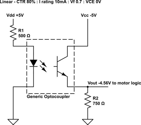
Transistor output opto-isolators use a phototransistor as the photosensitive device. When light from the LED falls on the phototransistor, it generates a collector current proportional to the light intensity. This type of opto-isolator is suitable for applications requiring higher output current and faster switching speeds.
2. Darlington Output Opto-Isolators
Darlington output opto-isolators use a Darlington transistor pair as the photosensitive device. A Darlington pair consists of two transistors connected in a cascaded configuration, providing higher current gain and sensitivity compared to a single transistor. This type of opto-isolator is suitable for applications requiring high output current and low input current.
3. TRIAC Output Opto-Isolators
TRIAC output opto-isolators use a TRIAC (triode for alternating current) as the output device. A TRIAC is a Bidirectional Switching device that can conduct current in both directions when triggered by a small gate current. This type of opto-isolator is commonly used for AC load control applications, such as dimming circuits and motor speed control.
4. Photodiode Output Opto-Isolators
Photodiode output opto-isolators use a photodiode as the photosensitive device. A photodiode generates a small current when exposed to light, which can be amplified using an external amplifier circuit. This type of opto-isolator is suitable for applications requiring high linearity and low noise, such as analog signal isolation.

Opto-Isolator Characteristics and Parameters
When selecting an opto-isolator for a specific application, several key characteristics and parameters should be considered:
1. Current Transfer Ratio (CTR)
The current transfer ratio (CTR) is the ratio of the output current to the input current of an opto-isolator. It represents the efficiency of the opto-isolator in converting the input signal to the output signal. CTR is typically expressed as a percentage and can vary depending on the input current, temperature, and other factors.
2. Isolation Voltage
The isolation voltage is the maximum voltage that can be applied between the input and output of an opto-isolator without causing electrical breakdown. It represents the level of electrical isolation provided by the opto-isolator. Typical isolation voltages range from a few hundred volts to several kilovolts.
3. Switching Speed
The switching speed of an opto-isolator refers to how quickly it can respond to changes in the input signal. It is usually specified in terms of rise time and fall time, which are the times required for the output signal to change from 10% to 90% and 90% to 10% of its final value, respectively. Faster switching speeds are desirable for applications requiring high-speed data transmission or precise timing control.
4. Bandwidth
The bandwidth of an opto-isolator is the range of frequencies over which it can effectively transmit signals. It is determined by the rise and fall times of the opto-isolator and is usually specified in terms of the -3dB frequency, which is the frequency at which the output signal amplitude is reduced to 70.7% of its maximum value.
5. Input-Output Capacitance
The input-output capacitance of an opto-isolator is the capacitance between its input and output terminals. This capacitance can limit the opto-isolator’s performance at high frequencies and can cause signal distortion or coupling of noise between the input and output circuits. Lower input-output capacitance is desirable for high-frequency applications.

Opto-Isolator Circuit Design Considerations
When designing circuits using opto-isolators, several factors should be considered to ensure optimal performance and reliability.
1. Input Current Limiting
The input current to the LED of an opto-isolator must be limited to prevent damage and ensure proper operation. A series resistor is typically used to limit the current based on the LED’s forward voltage drop and the input voltage. The resistor value can be calculated using Ohm’s law:
R = (Vin – Vf) / If
Where:
– R is the series resistor value
– Vin is the input voltage
– Vf is the LED’s forward voltage drop
– If is the desired forward current
2. Output Circuit Configuration
The output circuit of an opto-isolator can be configured in various ways depending on the application requirements. Common output circuit configurations include:
a. Pull-up resistor: A pull-up resistor is connected between the output and the positive supply voltage. This configuration is suitable for applications requiring a logic-level output signal.
b. Open-collector: The output transistor’s collector is left open, allowing it to be connected to an external load or pull-up resistor. This configuration is suitable for interfacing with other circuits or driving higher-current loads.
c. Totem-pole: The output stage consists of two transistors connected in a push-pull configuration, providing a low-impedance output signal suitable for driving loads directly.
3. Noise Immunity
Opto-isolators provide inherent noise immunity due to the electrical isolation between the input and output circuits. However, additional measures can be taken to further enhance noise immunity:
a. Proper grounding: Ensure that the input and output circuits have separate ground references to prevent ground loops and reduce noise coupling.
b. Shielding: Use shielded cables or enclosures to minimize the effects of electromagnetic interference (EMI) on the opto-isolator circuit.
c. Filtering: Implement filtering techniques, such as low-pass filters or ferrite beads, to suppress high-frequency noise on the input or output signals.
4. Temperature Effects
Opto-isolators are sensitive to temperature variations, which can affect their performance. The CTR and other parameters may change with temperature, leading to variations in the output signal. To minimize temperature effects:
a. Select opto-isolators with a wide operating temperature range and stable performance over temperature.
b. Use temperature compensation techniques, such as adding a temperature-sensitive component (e.g., a thermistor) to the input or output circuit.
c. Ensure proper heat dissipation and thermal management in the circuit design to avoid excessive temperature rises.

Opto-Isolator Application Examples
Opto-isolators find applications in various fields, including industrial control, automotive electronics, medical devices, and power systems. Some common application examples are:
1. Isolated GPIO Expansion
Opto-isolators can be used to expand the number of general-purpose input/output (GPIO) pins of a microcontroller or single-board computer while providing electrical isolation. This is particularly useful when interfacing with external sensors, actuators, or devices operating at different voltage levels or with potential ground loops.
2. Isolated RS-485 Communication
RS-485 is a popular serial communication standard used in industrial environments. Opto-isolators can be used to provide electrical isolation between the RS-485 transceiver and the host device, protecting against ground loops, voltage spikes, and other electrical disturbances that may damage the communication interface or corrupt data.
3. Solid-State Relay (SSR) Driver
Solid-state relays (SSRs) are electronic switches that use opto-isolators to provide isolation between the control input and the switching output. Opto-isolators are used to drive the SSR’s LED input, which in turn controls the output switching device (e.g., TRIAC or MOSFET). This allows the SSR to be controlled by low-voltage signals while switching high-voltage or high-current loads.
4. Isolated Analog Signal Transmission
Opto-isolators can be used to transmit analog signals between circuits while maintaining electrical isolation. Photodiode output opto-isolators are commonly used for this purpose due to their high linearity and low noise characteristics. The analog signal is converted to a light signal by modulating the LED current, and the photodiode output is then amplified and filtered to recover the original analog signal.
Opto-Isolator Selection Guide
When selecting an opto-isolator for a specific application, consider the following factors:
-
Input-output configuration: Choose an opto-isolator with the appropriate input and output characteristics (e.g., transistor, Darlington, TRIAC, or photodiode) based on the application requirements.
-
Isolation voltage: Ensure that the opto-isolator’s isolation voltage rating is sufficient for the application, considering the maximum voltage that may be present between the input and output circuits.
-
Current transfer ratio (CTR): Select an opto-isolator with a CTR suitable for the desired input-output current relationship. Higher CTR values provide greater output current for a given input current.
-
Switching speed: Consider the required switching speed of the application and choose an opto-isolator with compatible rise and fall times.
-
Bandwidth: For applications involving high-frequency signals, select an opto-isolator with adequate bandwidth to ensure minimal signal distortion.
-
Package type: Opto-isolators are available in various package types, such as DIP, SMD, and through-hole. Choose a package type that is compatible with the circuit board layout and assembly process.
-
Environmental factors: Consider the operating temperature range, humidity, and other environmental factors that may affect the opto-isolator’s performance, and select a device with appropriate ratings and specifications.
Opto-Isolator Manufacturers and Datasheets
Several manufacturers produce opto-isolators, each offering a range of devices with different specifications and characteristics. Some popular opto-isolator manufacturers include:
- Vishay Semiconductors
- Toshiba
- Broadcom (Avago)
- ON Semiconductor
- Renesas Electronics
- IXYS
- Lite-On
When designing circuits with opto-isolators, it is essential to refer to the manufacturer’s datasheets for detailed information on the device’s electrical and optical characteristics, absolute maximum ratings, and application guidelines. Datasheets provide valuable information on pin configurations, recommended operating conditions, typical performance curves, and example circuit diagrams.
Frequently Asked Questions (FAQ)
1. What is the purpose of an opto-isolator in a circuit?
An opto-isolator provides electrical isolation between two circuits while allowing signals to be transmitted between them using light. This isolation helps to protect sensitive circuits from voltage spikes, ground loops, and other electrical disturbances, as well as to interface circuits operating at different voltage levels.
2. How does an opto-isolator achieve electrical isolation?
An opto-isolator consists of an LED and a photosensitive device, such as a phototransistor or photodiode, encased in a single package. The LED and photosensitive device are optically coupled but electrically isolated. When the LED is energized, it emits light that is detected by the photosensitive device, which generates a corresponding electrical signal at its output. Since there is no direct electrical connection between the input and output circuits, electrical isolation is achieved.
3. What are the main types of opto-isolators?
The main types of opto-isolators are:
- Transistor output opto-isolators
- Darlington output opto-isolators
- TRIAC output opto-isolators
- Photodiode output opto-isolators
Each type has its unique characteristics and is suitable for different applications based on factors such as output current, switching speed, and linearity.
4. How do I select the appropriate opto-isolator for my application?
When selecting an opto-isolator, consider the following factors:
- Input-output configuration
- Isolation voltage
- Current transfer ratio (CTR)
- Switching speed
- Bandwidth
- Package type
- Environmental factors
Refer to the manufacturer’s datasheets for detailed specifications and application guidelines to ensure that the selected opto-isolator meets the requirements of your specific application.
5. Can opto-isolators be used for high-frequency signal transmission?
Yes, opto-isolators can be used for high-frequency signal transmission, but the maximum frequency is limited by the device’s bandwidth. Photodiode output opto-isolators are commonly used for high-frequency analog signal isolation due to their high linearity and low noise characteristics. When selecting an opto-isolator for high-frequency applications, consider the device’s bandwidth, rise and fall times, and input-output capacitance to ensure minimal signal distortion.
Conclusion
Opto-isolators are essential components in a wide range of electronic circuits, providing electrical isolation and signal transmission capabilities. Understanding the working principles, types, and characteristics of opto-isolators is crucial for designing reliable and efficient circuits.
When designing circuits with opto-isolators, consider factors such as input current limiting, output circuit configuration, noise immunity, and temperature effects. Proper selection of opto-isolators based on application requirements, isolation voltage, CTR, switching speed, and other parameters ensures optimal performance and reliability.
Opto-isolators find applications in various fields, including industrial control, automotive electronics, medical devices, and power systems. They are used for isolated GPIO expansion, isolated RS-485 communication, solid-state relay driving, and isolated analog signal transmission, among other applications.
By referring to manufacturer datasheets and application notes, designers can effectively integrate opto-isolators into their circuits and harness their isolation and signal transmission capabilities. As technology advances, opto-isolators continue to evolve, offering improved performance, smaller packages, and new features to meet the growing demands of modern electronic systems.


Leave a Reply