Introduction
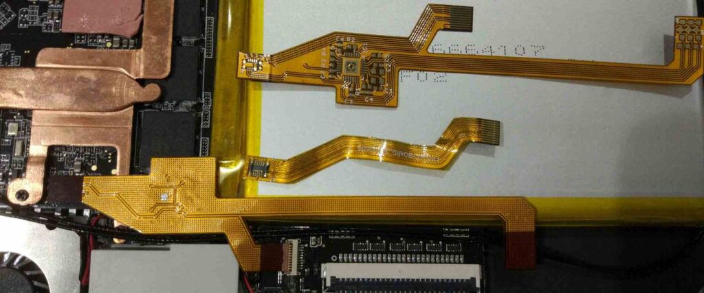
Flex circuits, also known as flexible printed circuits (FPCs), are a type of printed circuit board (PCB) made with flexible dielectric materials. Unlike traditional rigid PCBs, flex circuits can bend and flex to fit mechanical designs with dynamic parts or tight spaces. Multilayer flex circuits take this technology a step further by stacking two or more circuit layers together.
Multilayer flex circuits provide a number of advantages over single layer flex and rigid boards. By allocating signals across multiple layers, routing is simplified, more compact, and overall board layout is optimized. Multilayer FPCs also allow for higher component density by enabling components to be placed on both sides of the board. The combination of flexibility and multilayer design makes this technology ideal for complex and miniaturized electronics in consumer, automotive, aerospace, medical, and industrial applications.
This article will provide an in-depth look at multilayer flex circuit technology, manufacturing processes, design considerations, applications, and future trends.
What are Multilayer Flex Circuits?

A multilayer flex circuit consists of two or more conductive copper layers separated by flexible dielectric layers. The dielectric materials used include polyimide, polyester, and fluoropolymer films. Conductive paths and traces are etched into the copper foil layers to provide electrical connections between components. Vias are plated through holes in the dielectric layers that provide vertical interconnections between the copper layers. Figure 1 below shows a cross-section of a typical 4-layer multilayer flex circuit.<img src=”multilayerflex.png” alt=”Multilayer flex circuit cross-section” width=”400″>
Figure 1: Cross-section of a 4-layer multilayer flex circuit showing copper layers, dielectric layers, and plated through-hole vias.
Multilayer flex circuits typically range from 2 to 12 or more circuit layers. Some key terms associated with multilayer flex circuits include:
- Dielectric layers: The insulating polymer films that separate the copper foil layers. Typical materials are polyimide and polyester films.
- Copper foil: Thin sheets of copper bonded to the dielectric layers and etched to form circuits. Standard thicknesses range from 1/4 oz (9 μm) to 2 oz (70 μm) copper.
- Adhesive: An acrylic or epoxy adhesive bonds the copper foil to the dielectric layers.
- Vias: Plated through holes in the dielectric layers that provide electrical connections between copper layers.
- Stiffener: A thicker polyimide or metal sheet laminated to one side of the flex circuit to provide mechanical support.
- Cover layer: A thin protective layer of polymer laminated over the outermost circuit layer.
Manufacturing Processes
Multilayer flex circuits require specialized processes to manufacture the layered design. While specific techniques vary between fabricators, there are four primary steps to produce multilayer flex circuits:
1. Fabrication of Dielectric and Copper Foil Layers
The flexible dielectric substrate (usually polyimide or polyester) is produced into thin sheets. Rolls of copper foil are bonded to the dielectric layers using adhesive. The thickness of the dielectric and copper foils determines flexural strength, electrical properties, and cost.
2. Circuit Imaging
Using photolithographic processes adapted from rigid PCB fabrication, circuits are imaged onto the copper layers. A photosensitive polymer resist is applied, exposed to UV light through a mask, and chemically etched to remove unwanted copper, leaving behind the desired circuit traces.
3. Lamination
Individual flex circuit layers are precisely aligned and laminated together using heat and pressure. Registration accuracy requirements are much tighter than with rigid multilayer boards. Drilled or punched holes are plated to form vertical interconnect vias between layers.
4. Final Assembly
Stiffeners and cover layers may be added for mechanical support and protection. Components are sometimes assembled onto the flex circuit boards through soldering, conductive adhesive bonding, or mechanical attachment. Electrical testing validates the multilayer circuit functionality.
Design Considerations
Designing multilayer flex circuits requires special considerations in layout, routing, and material selection compared to rigid PCBs:
- Small features: Trace/space is often 5 mils (0.13 mm) or smaller to maximize circuit density in the flexible layers.
- Tight registration: Hole to pad registration must be very precise across flex layers, often within 0.5 mils.
- Dynamic flexing: The circuit must be designed to flex repeatedly at certain points without fatiguing and cracking.
- Material properties: Dielectric strength, modulus, moisture absorption, coefficients of thermal expansion (CTEs), and Z-axis coefficients of expansion (ZAEs) are important parameters.
- Routing: Escape routing from dense BGAs and other components can be challenging on flex layers. Planning ahead for routing is critical.
- Shielding: Sensitive signals may need shielding layers between other traces or ground planes to reduce EMI and noise.
- Stiffening: Thicker dielectric layers, stiffeners, and metal backing can be used to control flexibility in certain areas.
- Testing: In-circuit tests, flying probe tests, and bed-of-nails fixtures will require specialized adapters.
Applications of Multilayer Flex Circuits
Some of the many products utilizing multilayer flex circuit technology include:
- Consumer electronics – Mobile phones, laptops, tablets, cameras, wearables. Allows compact, lightweight interconnections and dynamic flexing.
- Automotive – Engine control units, lane departure warning systems, navigation and entertainment systems. Meets reliability needs in harsh environments.
- Medical – Hearing aids, blood glucose monitors, portable medical devices. Provides excellent biocompatibility and size.
- Aerospace/military – Avionics systems, radar systems, satellite systems. Withstands vibration, thermal cycling, and flexing forces.
- Industrial – Robotics, automation equipment, test and measurement equipment. Suits complex motion control and small spaces.
Table 1 summarizes some of the typical applications and requirements associated with multilayer flex circuits in various industries:
| Industry | Typical Applications | Key Requirements |
|---|---|---|
| Consumer Electronics | Smartphones, wearables, game controllers | Compact size, dynamic/repeated flexing, cost |
| Automotive | Engine control units, displays | Reliability, vibration resistance, temperature range |
| Aerospace/Military | Avionics, radar, weapons systems | Reliability, thermal cycling, flexure |
| Medical | Hearing aids, blood analysis devices | Biocompatibility, compact size, moisture resistance |
| Industrial | Robotics, machine controls, sensors | Flexibility, corrosion resistance, EMI shielding |
Table 1: Multilayer flex circuit applications across industries
Future Trends

Several technology trends are influencing the development of multilayer flex circuits:
- Finer lines and spaces: Fabricators continue to reduce trace widths and spacings to 5 mils or below using advanced processes. This allows for more layers and interconnects.
- High density interconnects (HDI): Laser drilled microvias combined with finer lines enable higher interconnect densities. HDI flex circuits can approach 1000+ connections per square inch.
- Rigid-flex integration: Combining rigid and flex layers into one circuit expands PCB possibilities. Flexible “hinges” connect rigid sections containing components.
- Additive processes: Additive methods deposit circuit traces only where needed instead of etching away unwanted copper. This further enables fine features and tolerances.
- New materials: Flexible glass substrates and liquid crystal polymer (LCP) films provide superior dimensional and thermal stability compared to polyimide films.
As electronics evolve toward smaller, faster, and more dynamic designs, multilayer flex circuits will continue growing in capabilities and applications across many industries. With their inherent advantages, multilayer flex circuits are positioned to enable many emerging technologies and systems.
Conclusion
Multilayer flex circuits merge the benefits of flexible circuits and multilayer boards to meet the interconnect needs of complex and miniaturized electronics. Polymer dielectric layers bonded with conductive copper foils etched into circuits allow flexible stacking of multiple circuit layers. Using specialized processes adapted from rigid PCB fabrication, multilayer flex circuits achieve reliable vertical interconnections within extremely tight tolerances. While demanding in design and manufacture, multilayer flex technology provides invaluable size, weight, reliability, and functionality advantages across consumer, automotive, aerospace, medical, and industrial applications. Ongoing innovations in materials, fabrication methods, and integration with other technologies will unlock even greater possibilities with multilayer flex circuits.
Frequently Asked Questions
Here are some common questions about multilayer flex circuits:
Q: How many layers can be built in a multilayer flex circuit?
A: Most multilayer flex circuits have 2 to 12 layers, though some can have 20 layers or more. As layer count increases, the flex circuit becomes thinner but more challenging to manufacture.
Q: What are some key differences in designing a multilayer flex vs. a rigid multilayer PCB?
A: Multilayer flex circuits require tighter tolerances, dynamic flexure analysis, smaller features, layer-to-layer registration accuracy, and specialized materials. Shielding, routing, and escape patterns also require unique design considerations.
Q: What are rigid-flex circuits?
A: Rigid-flex circuits integrate rigid FR-4 PCB sections with flexible circuit sections, typically connected by a foldable flexible “hinge”. This allows rigid mounted components to interface with dynamic flexing regions.
Q: Can components be mounted on multilayer flex circuits?
A: Yes, components can be surface mounted to the outer circuit layers or into cutouts. But the boards cannot be wave soldered, so reflow soldering or conductive adhesive mounting are used.
Q: How are multilayer flex circuits tested?
A: Flying probe testers, bed-of-nails fixtures, and point-to-point probing allow electronic testing of multilayer flex circuits. Test fixtures require careful design to avoid damaging flexible boards.


Leave a Reply