What is I2S?
I2S, which stands for Inter-IC Sound, is a serial bus interface standard used for connecting digital audio devices. It is commonly used to transfer audio data between integrated circuits in an electronic device.
I2S was originally developed by Philips Semiconductors (now NXP Semiconductors) in 1986 and has since become a widely adopted standard in the audio industry. It provides a simple and efficient way to transmit high-quality digital audio between devices, such as microprocessors, digital signal processors (DSPs), codecs, and digital-to-analog converters (DACs).
Key Features of I2S
- Supports high-quality digital audio transmission
- Simple and efficient interface
- Widely adopted in the audio industry
- Flexible configuration options
- Low power consumption
How Does I2S Work?
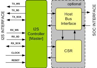
I2S uses a master-slave architecture, where one device acts as the master and controls the communication, while the other devices act as slaves and follow the master’s instructions. The master device generates the clock signals and initiates the data transfer, while the slave devices synchronize their operations with the master’s clock and respond to the data transfer requests.
I2S Bus Lines
The I2S interface consists of three main bus lines:
- Serial Clock (SCK or BCLK): This line carries the clock signal generated by the master device, which synchronizes the data transmission between the devices.
- Word Select (WS or LRCLK): This line indicates the start of a new audio frame and determines the left and right channel data. It is typically toggled at the sample rate frequency.
- Serial Data (SD or SDATA): This line carries the actual audio data being transmitted between the devices. The data is sent in a serial format, one bit at a time.
Some I2S implementations may also include an additional line called Master Clock (MCLK), which provides a higher-frequency reference clock to the devices for synchronization purposes.
I2S Data Format
I2S uses a fixed data format for transmitting audio samples. Each audio sample is typically represented by 16, 24, or 32 bits, depending on the audio resolution. The most significant bit (MSB) is transmitted first, followed by the lower bits.
The I2S data format consists of two subframes, one for the left channel and one for the right channel. The Word Select (WS) line determines which subframe is being transmitted. When WS is low, the left channel data is transmitted, and when WS is high, the right channel data is transmitted.
| WS | Left Channel | Right Channel |
|---|---|---|
| Low | MSB … LSB | |
| High | MSB … LSB |
I2S Timing Diagram
The following timing diagram illustrates the relationship between the I2S bus lines during data transmission:
    +---+   +---+   +---+   +---+   +---+   +---+   +---+   +---+   +---+
SCK |   |   |   |   |   |   |   |   |   |   |   |   |   |   |   |   |   |
    +---+   +---+   +---+   +---+   +---+   +---+   +---+   +---+   +---+

      +-------+       +-------+       +-------+       +-------+       +---
WS    |       |       |       |       |       |       |       |       |
      +-------+       +-------+       +-------+       +-------+       +---

        +-------+     +-------+       +-------+     +-------+     +-------
SD      | Left  |     | Right |       | Left  |     | Right |     | Left
        +-------+     +-------+       +-------+     +-------+     +-------
In this diagram:
– SCK represents the Serial Clock line, which toggles at the bit clock frequency.
– WS represents the Word Select line, which toggles at the sample rate frequency and determines the left and right channel data.
– SD represents the Serial Data line, which carries the audio data bits. The data bits are aligned with the rising or falling edge of SCK, depending on the I2S configuration.

Configuring I2S
I2S offers several configuration options to accommodate different audio system requirements. The main configuration parameters include:
- Sample Rate: The sample rate determines the number of audio samples per second. Common sample rates include 44.1 kHz (CD quality), 48 kHz, 96 kHz, and 192 kHz.
- Word Length: The word length specifies the number of bits per audio sample. Typical word lengths are 16, 24, and 32 bits.
- Clock Polarity: The clock polarity determines whether the data is transmitted on the rising or falling edge of the serial clock (SCK).
- Bit Order: The bit order specifies whether the most significant bit (MSB) or least significant bit (LSB) is transmitted first.
Setting the Sample Rate
The sample rate is determined by the frequency of the Word Select (WS) line. The I2S master device generates the WS signal at the desired sample rate frequency. For example, for a sample rate of 44.1 kHz, the WS line would toggle at a frequency of 44.1 kHz.
Setting the Word Length
The word length is configured by setting the appropriate number of bits per audio sample. This is typically done through the configuration registers of the I2S devices. The word length must be agreed upon by all the devices participating in the I2S communication.
Setting the Clock Polarity
The clock polarity determines the edge of the serial clock (SCK) on which the data is transmitted. There are two options:
- Rising Edge: The data is transmitted on the rising edge of SCK.
- Falling Edge: The data is transmitted on the falling edge of SCK.
The clock polarity is usually configurable through the I2S device’s configuration registers or by selecting the appropriate I2S mode.
Setting the Bit Order
The bit order determines the order in which the bits of an audio sample are transmitted. There are two options:
- MSB First: The most significant bit (MSB) is transmitted first, followed by the lower bits.
- LSB First: The least significant bit (LSB) is transmitted first, followed by the higher bits.
The bit order is usually configurable through the I2S device’s configuration registers or by selecting the appropriate I2S mode.

Advantages of Using I2S
I2S offers several advantages over other audio interfaces:
- High-Quality Audio: I2S supports high-resolution audio formats, allowing for the transmission of high-quality digital audio with minimal degradation.
- Simple and Efficient: I2S uses a simple and efficient interface, requiring only three main bus lines for data transmission. This simplicity reduces the complexity of hardware designs and minimizes the number of interconnects between devices.
- Low Power Consumption: I2S is designed to minimize power consumption, making it suitable for portable and battery-powered devices.
- Widely Adopted: I2S is a widely adopted standard in the audio industry, ensuring compatibility between various audio devices and components.

Applications of I2S
I2S is used in a wide range of applications, including:
- Digital Audio Players: I2S is commonly used in digital audio players, such as MP3 players, portable media players, and home audio systems, to transfer audio data between the processor and the DAC.
- Smartphones and Tablets: I2S is used in smartphones and tablets to interface the audio codec with the application processor, enabling high-quality audio playback and recording.
- Professional Audio Equipment: I2S is used in professional audio equipment, such as mixing consoles, digital audio workstations, and audio interfaces, to interconnect various audio components and ensure high-fidelity audio transmission.
- Automotive Audio Systems: I2S is used in automotive audio systems to transmit audio data between the head unit, amplifiers, and speakers, providing high-quality audio playback in vehicles.
- Home Theater Systems: I2S is used in home theater systems to connect the audio processor with the DACs and amplifiers, enabling multi-channel audio playback.
I2S vs. Other Audio Interfaces
I2S is one of several digital audio interfaces used in electronic devices. Here’s a comparison of I2S with some other common audio interfaces:
I2S vs. PCM
PCM (Pulse Code Modulation) is a general term for digital audio encoding, while I2S is a specific interface standard for transmitting PCM audio data between devices.
- PCM refers to the method of encoding analog audio signals into digital form, while I2S defines the physical interface and protocol for transmitting PCM audio data.
- I2S is a standardized interface specifically designed for audio data transmission, while PCM can be transmitted over various interfaces, such as I2S, SPI, or custom protocols.
I2S vs. SPI
SPI (Serial Peripheral Interface) is a general-purpose serial interface that can be used for transmitting audio data, but it has some differences compared to I2S.
- SPI is a full-duplex interface, allowing simultaneous bidirectional communication, while I2S is a simplex interface, supporting unidirectional data transmission.
- SPI requires four lines (MOSI, MISO, SCK, CS), while I2S typically uses three lines (SCK, WS, SD).
- SPI does not have a standardized format for audio data, requiring custom protocols, while I2S has a standardized data format specifically designed for audio.
I2S vs. TDM
TDM (Time Division Multiplexing) is a method of transmitting multiple audio channels over a single data line, while I2S is designed for transmitting stereo audio (two channels).
- TDM allows for the transmission of multiple audio channels by dividing the data line into time slots, each carrying a single channel’s data.
- I2S is limited to two audio channels (left and right) and does not natively support multi-channel audio transmission.
- TDM requires additional synchronization and demultiplexing logic compared to I2S.
Implementing I2S
To implement I2S communication between devices, follow these general steps:
- Identify the I2S master and slave devices in your system.
- Connect the I2S bus lines (SCK, WS, SD) between the master and slave devices.
- Configure the I2S parameters (sample rate, word length, clock polarity, bit order) in the master and slave devices.
- Enable the I2S peripheral in the master device and initiate the data transmission.
- Ensure that the slave devices are properly synchronized with the master’s clock and responding to the data transfer requests.
Here’s a simplified example of I2S configuration and data transmission using an embedded microcontroller as the master and a DAC as the slave:
// I2S Configuration
void i2s_init(void) {
    // Enable I2S peripheral clock
    // Configure I2S pins (SCK, WS, SD)
    // Set I2S mode (master)
    // Set I2S standard (Philips)
    // Set I2S data format (16-bit, MSB first)
    // Set I2S clock polarity and phase
    // Set I2S sample rate
    // Enable I2S peripheral
}

// I2S Data Transmission
void i2s_send_data(uint16_t left_data, uint16_t right_data) {
    // Wait for I2S transmit buffer to be empty
    // Write left channel data to I2S transmit buffer
    // Write right channel data to I2S transmit buffer
}
In this example, the i2s_init() function configures the I2S peripheral of the microcontroller, setting the desired parameters such as mode, standard, data format, clock polarity, and sample rate.
The i2s_send_data() function demonstrates how to transmit audio data over I2S. It waits for the I2S transmit buffer to be empty and then writes the left and right channel data to the buffer. The I2S peripheral automatically handles the transmission of the data according to the configured parameters.
Troubleshooting I2S
If you encounter issues while working with I2S, here are some common problems and troubleshooting tips:
- No Audio Output:
- Check the physical connections between the I2S devices, ensuring that the bus lines (SCK, WS, SD) are properly connected.
- Verify that the I2S configuration parameters (sample rate, word length, clock polarity, bit order) match between the master and slave devices.
- Ensure that the I2S peripheral is enabled and properly initialized in the master device.
-
Check if the slave device (e.g., DAC) is properly powered and configured.
-
Distorted or Noisy Audio:
- Ensure that the I2S configuration parameters match the audio format of the source data.
- Check for any clock synchronization issues between the master and slave devices.
- Verify that the I2S bus lines are properly shielded and routed to minimize interference.
-
Use appropriate pull-up or pull-down resistors on the I2S bus lines if required.
-
Intermittent or Stuttering Audio:
- Ensure that the I2S data transmission is continuous and uninterrupted.
- Check for any buffer underrun or overrun conditions in the master or slave devices.
- Optimize the I2S data handling and processing to minimize latency and avoid audio dropouts.
-
Verify that the system has sufficient processing power and memory to handle the audio data transmission.
-
Incompatibility Between Devices:
- Make sure that the I2S devices are compatible and support the same I2S standards and configurations.
- Check the device datasheets and application notes for any specific requirements or limitations.
- Consider using I2S interface ICs or converters to bridge compatibility gaps between devices.
FAQ
-
Q: Is I2S compatible with other audio interfaces like I2C or SPI?
A: I2S is a dedicated audio interface and is not directly compatible with I2C or SPI. However, some devices may support multiple interfaces, including I2S, I2C, or SPI, for audio data transmission. -
Q: Can I2S transmit compressed audio formats like MP3 or AAC?
A: I2S is designed for transmitting uncompressed PCM audio data. To transmit compressed audio formats, you would need to decompress the audio data before sending it over I2S. -
Q: What is the maximum sample rate supported by I2S?
A: The maximum sample rate supported by I2S depends on the capabilities of the devices involved. Common sample rates range from 44.1 kHz to 192 kHz, but some high-end audio devices may support even higher sample rates. -
Q: How long can the I2S bus lines be?
A: The maximum length of the I2S bus lines depends on factors such as the clock frequency, bus capacitance, and signal integrity. It is generally recommended to keep the I2S bus lines as short as possible to minimize signal degradation and ensure reliable data transmission. -
Q: Can I use I2S for multi-channel audio transmission?
A: I2S natively supports stereo audio (two channels) transmission. For multi-channel audio, you can consider using other interface standards like TDM (Time Division Multiplexing) or using multiple I2S interfaces for each audio channel.
Conclusion
I2S is a widely used digital audio interface that provides a simple and efficient way to transmit high-quality audio data between devices. By understanding the I2S protocol, its configuration options, and implementation techniques, you can effectively integrate I2S into your audio projects and ensure seamless audio communication between components.
When working with I2S, pay attention to the configuration parameters, such as sample rate, word length, clock polarity, and bit order, to ensure compatibility between devices. Proper wiring and signal integrity are also crucial for reliable I2S communication.
I2S finds applications in various domains, including consumer electronics, professional audio equipment, automotive systems, and more. Its simplicity, efficiency, and widespread adoption make it a popular choice for digital audio transmission.
As you delve deeper into I2S and gain hands-on experience, you’ll be able to leverage its capabilities to create high-quality audio systems and deliver immersive audio experiences to users.


Leave a Reply