Introduction to EagleCAD
EagleCAD is a powerful electronic design automation (EDA) software that enables users to create professional-grade printed circuit board (PCB) layouts and schematic diagrams. Developed by CadSoft Computer GmbH, which was later acquired by Autodesk, EagleCAD has become a popular choice among electronics enthusiasts, hobbyists, and professionals due to its user-friendly interface, extensive library of components, and robust features.
Key Features of EagleCAD
- Schematic Editor
- PCB Layout Editor
- Extensive Component Libraries
- Design Rule Checking (DRC)
- Autorouter
- 3D Visualization
- Multi-sheet Schematic Support
- Hierarchical Design
- Scripting Support
- Cross-platform Compatibility
Getting Started with EagleCAD
System Requirements
Before installing EagleCAD, ensure that your computer meets the following minimum system requirements:
| Operating System | Processor | RAM | Hard Disk Space |
|---|---|---|---|
| Windows 7/8/10 | 1 GHz | 2 GB | 500 MB |
| macOS 10.11+ | 1 GHz | 2 GB | 500 MB |
| Linux | 1 GHz | 2 GB | 500 MB |
Installation Process
- Download the appropriate version of EagleCAD for your operating system from the official Autodesk website.
- Run the installer and follow the on-screen instructions to complete the installation process.
- Launch EagleCAD and activate your license using the provided serial number or sign in with your Autodesk account.

Navigating the EagleCAD Interface
Main Window
The main window of EagleCAD consists of several key areas:
- Menu Bar
- Toolbar
- Control Panel
- Editor Window
- Status Bar
Schematic Editor
The schematic editor is used to create and edit electronic circuits. It provides a set of tools for placing components, drawing wires, and adding labels and annotations.
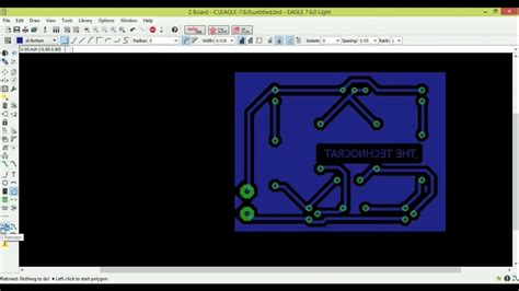
PCB Layout Editor
The PCB layout editor is used to design the physical layout of the PCB. It allows users to place components, route traces, and define board dimensions and layers.

Creating a Schematic
Adding Components
- Open the schematic editor by clicking on the “Schematic” button in the control panel.
- Use the “Add” tool to place components from the libraries onto the schematic canvas.
- Customize the component properties, such as value and package, using the “Properties” dialog.
Connecting Components
- Use the “Wire” tool to draw connections between the component pins.
- Add labels and annotations to clarify the function of each connection.
- Use the “Net” tool to assign names to the connected wires.
Hierarchical Design
For complex designs, EagleCAD supports hierarchical schematics, allowing users to break down the circuit into smaller, more manageable sub-circuits.
- Create a new schematic sheet for each sub-circuit.
- Use the “Symbol” tool to create a custom symbol representing the sub-circuit.
- Place the custom symbol on the main schematic and connect it to the rest of the circuit.

Designing the PCB Layout
Board Setup
- Open the PCB layout editor by clicking on the “Board” button in the control panel.
- Define the board dimensions and layers using the “Board” and “Layers” settings.
- Place mounting holes and other mechanical features as required.
Component Placement
- Use the “Move” tool to arrange the components on the PCB according to the schematic.
- Ensure proper spacing between components to facilitate routing and manufacturing.
- Use the “Rotate” and “Mirror” tools to orient the components as needed.
Routing Traces
- Use the “Route” tool to manually draw traces between the component pads.
- Adjust the trace width and clearance settings to meet the design requirements.
- Use the “Autorouter” tool to automatically route the remaining connections.
Design Rule Checking (DRC)
- Define the design rules, such as minimum trace width and clearance, using the “DRC” settings.
- Run the DRC to identify and resolve any design rule violations.
- Iterate the design process until all violations are resolved.
Generating Output Files
Gerber Files
- Go to “File” > “CAM Processor” to open the CAM Processor window.
- Select the appropriate Gerber file format and settings.
- Generate the Gerber files for each layer of the PCB.
Drill Files
- In the CAM Processor window, select the “Excellon” drill file format.
- Generate the drill files for the PCB.
Bill of Materials (BOM)
- Go to “File” > “Export” > “BOM” to open the BOM export dialog.
- Choose the desired BOM format and options.
- Export the BOM file for use in procurement and assembly.
Best Practices and Tips
- Use a consistent naming convention for components, nets, and layers.
- Keep the schematic organized and easy to read by using labels and annotations.
- Follow the manufacturer’s recommended design guidelines for your chosen PCB fabrication process.
- Use the 3D visualization feature to check for component clearance and mechanical fit.
- Regularly save and back up your design files to prevent data loss.
Frequently Asked Questions (FAQ)
1. Is EagleCAD free to use?
EagleCAD offers a free version for non-commercial use, with limitations on board size and layer count. For commercial use or advanced features, a paid subscription is required.
2. Can EagleCAD import designs from other EDA software?
Yes, EagleCAD can import schematic and PCB designs from various formats, including Altium Designer, KiCad, and Mentor Graphics PADS.
3. Does EagleCAD support multi-layer PCBs?
Yes, EagleCAD supports the design of multi-layer PCBs, with up to 16 signal layers in the standard version and unlimited layers in the premium version.
4. Can I create custom components in EagleCAD?
Yes, EagleCAD allows users to create custom components and add them to the library for future use. This can be done using the “Symbol” and “Package” editors.
5. Is there a way to automate repetitive tasks in EagleCAD?
Yes, EagleCAD supports scripting using the User Language Program (ULP) format. Users can create custom scripts to automate tasks, such as generating BOM files or applying design rule checks.
Conclusion
EagleCAD is a versatile and user-friendly EDA software that simplifies the process of designing electronic circuits and PCBs. By following the steps outlined in this article, you can quickly get started with EagleCAD and create professional-grade designs for your projects. Remember to adhere to best practices, regularly save your work, and take advantage of the software’s advanced features to streamline your design process. With practice and experience, you’ll be able to harness the full potential of EagleCAD and bring your electronic ideas to life.


Leave a Reply