Introduction to Thermal Conductivity in Printed Wiring Boards
Printed Wiring Boards (PWBs), also known as Printed Circuit Boards (PCBs), are essential components in modern electronic devices. They provide mechanical support and electrical connectivity for electronic components. As electronic devices become more compact and powerful, managing heat dissipation becomes a critical concern. Thermal conductivity plays a crucial role in the efficient transfer of heat away from electronic components, ensuring their reliable operation and longevity. In this article, we will explore the concept of thermal conductivity in PWBs and discuss methods for calculating it.
What is Thermal Conductivity?
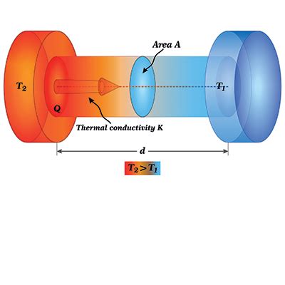
Thermal conductivity is a material property that describes the ability of a substance to conduct heat. It is defined as the rate of heat transfer through a material per unit thickness, per unit area, and per unit temperature difference. The SI unit for thermal conductivity is watts per meter-kelvin (W/mK). Materials with high thermal conductivity allow heat to flow easily, while materials with low thermal conductivity act as thermal insulators.
Importance of Thermal Conductivity in PWBs
In PWBs, thermal conductivity is essential for several reasons:
-
Heat Dissipation: Electronic components generate heat during operation. If this heat is not effectively dissipated, it can lead to component failure, reduced performance, and shortened lifespan. PWBs with high thermal conductivity help transfer heat away from components, preventing overheating.
-
Temperature Uniformity: Uneven temperature distribution across a PWB can cause thermal stress and warping. Materials with good thermal conductivity promote uniform temperature distribution, minimizing thermal gradients and reducing the risk of mechanical failures.
-
Signal Integrity: High temperatures can affect the electrical properties of components and conductors, leading to signal degradation and increased noise. Effective thermal management through high thermal conductivity helps maintain signal integrity by keeping temperatures within acceptable limits.
Factors Affecting Thermal Conductivity in PWBs
Several factors influence the thermal conductivity of PWBs:
Material Properties
The thermal conductivity of a PWB depends on the properties of the materials used in its construction. The most common materials used in PWBs are:
-
Copper: Copper is widely used for conducting layers in PWBs due to its excellent electrical and thermal conductivity. The thermal conductivity of copper is approximately 400 W/mK.
-
Dielectric Substrate: The dielectric substrate, such as FR-4, provides electrical insulation and mechanical support. FR-4 has a relatively low thermal conductivity of around 0.3 W/mK.
-
Solder Mask: Solder mask is a thin layer applied over the copper traces to protect them from oxidation and prevent solder bridging. Solder mask materials typically have low thermal conductivity.
-
Thermal Interface Materials (TIMs): TIMs, such as Thermal Pads or Thermal Adhesives, are used to enhance heat transfer between components and the PWB. The thermal conductivity of TIMs can vary widely depending on their composition.
Board Thickness and Layer Stack-up
The thickness of the PWB and the arrangement of its layers also affect thermal conductivity. Thicker boards generally have lower thermal conductivity due to the increased distance heat must travel. The placement of high thermal conductivity layers, such as copper planes, can also impact the overall thermal performance of the board.
Copper Thickness and Coverage
The thickness and coverage of the copper layers in a PWB influence its thermal conductivity. Thicker copper layers provide better heat spreading capabilities, while higher copper coverage allows for more efficient heat transfer.
Via Density and Placement
Thermal vias are conductive pathways that transfer heat through the thickness of the PWB. The density and placement of thermal vias can significantly affect the board’s thermal conductivity. Strategically placed thermal vias near heat-generating components can improve heat dissipation.

Methods for Calculating Thermal Conductivity in PWBs
There are several methods for calculating the thermal conductivity of PWBs, ranging from analytical calculations to numerical simulations. Let’s explore some of these methods:
Analytical Methods
Analytical methods involve using mathematical equations to estimate the thermal conductivity of a PWB based on its material properties and geometry. One common analytical approach is the Effective Thermal Conductivity (ETC) method.
The ETC method calculates the thermal conductivity of a multi-layer PWB by considering it as a composite material. It takes into account the thermal conductivities and thicknesses of each layer. The ETC can be calculated using the following equation:
ETC = (Σ(ki * ti)) / (Σti)
Where:
– ki is the thermal conductivity of layer i
– ti is the thickness of layer i
For example, consider a two-layer PWB with the following properties:
– Layer 1: Copper, thermal conductivity = 400 W/mK, thickness = 0.035 mm
– Layer 2: FR-4, thermal conductivity = 0.3 W/mK, thickness = 1.565 mm
Using the ETC equation, we can calculate the effective thermal conductivity:
ETC = (400 * 0.035 + 0.3 * 1.565) / (0.035 + 1.565)
     = (14 + 0.4695) / 1.6
     = 9.0435 W/mK
Numerical Simulations
Numerical simulations involve using computational methods to model the thermal behavior of a PWB. These simulations provide a more accurate representation of the temperature distribution and heat flow within the board. Two commonly used numerical simulation techniques are Finite Element Analysis (FEA) and Computational Fluid Dynamics (CFD).
Finite Element Analysis (FEA)
FEA is a numerical method that divides the PWB into small elements and solves the heat transfer equations for each element. It considers the geometry, material properties, and boundary conditions of the board. FEA simulations can provide detailed temperature maps and help identify hot spots.
To perform an FEA simulation for thermal conductivity calculation, follow these steps:
- Create a 3D model of the PWB, including the layout, layer stack-up, and component placement.
- Assign material properties, including thermal conductivity, to each layer and component.
- Define boundary conditions, such as ambient temperature and heat generation from components.
- Mesh the model into small elements.
- Solve the heat transfer equations using FEA software.
- Analyze the temperature distribution and calculate the effective thermal conductivity.
Computational Fluid Dynamics (CFD)
CFD simulations model the fluid flow and heat transfer in and around the PWB. They consider factors such as airflow, convection, and radiation. CFD simulations are particularly useful when evaluating the thermal performance of PWBs in enclosures or with active cooling solutions.
To perform a CFD simulation for thermal conductivity calculation, follow these steps:
- Create a 3D model of the PWB and its surrounding environment.
- Assign material properties, including thermal conductivity, to each component.
- Define fluid properties, such as air density and viscosity.
- Set up boundary conditions, including inlet and outlet airflow and heat sources.
- Generate a mesh to discretize the computational domain.
- Solve the governing equations for fluid flow and heat transfer using CFD software.
- Analyze the temperature distribution and calculate the effective thermal conductivity.

Experimental Measurements
In addition to analytical and numerical methods, experimental measurements can be used to determine the thermal conductivity of PWBs. One commonly used technique is the Guarded Hot Plate (GHP) method.
The GHP method involves placing a PWB sample between two plates, one heated and one cooled. The heat flow through the sample is measured, and the thermal conductivity is calculated based on the temperature gradient and sample thickness.
To perform a GHP measurement, follow these steps:
- Prepare a PWB sample of known dimensions.
- Place the sample between the heated and cooled plates of the GHP apparatus.
- Apply a known heat flux to the heated plate and maintain a steady-state temperature gradient across the sample.
- Measure the temperatures of the plates and the sample thickness.
- Calculate the thermal conductivity using Fourier’s law of heat conduction.

Best Practices for Improving Thermal Conductivity in PWBs
To enhance the thermal conductivity of PWBs and improve heat dissipation, consider the following best practices:
-
Use High Thermal Conductivity Materials: Select materials with high thermal conductivity, such as copper, for the conducting layers and thermal interface materials.
-
Optimize Copper Thickness and Coverage: Increase the thickness of copper layers and maximize copper coverage to improve heat spreading.
-
Incorporate Thermal Vias: Use thermal vias strategically placed near heat-generating components to provide efficient heat transfer through the board.
-
Minimize Thermal Resistance: Reduce the thermal resistance between components and the PWB by using thermal interface materials and ensuring good contact.
-
Consider Metal Core Substrates: For applications with high heat dissipation requirements, consider using metal core substrates, such as aluminum or copper, which have higher thermal conductivity than traditional FR-4.
-
Optimize Layer Stack-up: Arrange the layers in the PWB stack-up to maximize heat transfer. Place high thermal conductivity layers, such as copper planes, close to heat-generating components.
-
Utilize Thermal Simulations: Perform thermal simulations using FEA or CFD to analyze the temperature distribution and identify areas for improvement in the PWB design.
Frequently Asked Questions (FAQ)
-
What is the difference between thermal conductivity and thermal resistance?
Thermal conductivity is a material property that describes the ability of a substance to conduct heat, while thermal resistance is a measure of a material’s opposition to heat flow. Thermal resistance is the reciprocal of thermal conductivity. -
How does the thickness of a PWB affect its thermal conductivity?
Generally, thicker PWBs have lower thermal conductivity because heat has to travel a longer distance through the board. However, the overall thermal performance also depends on factors such as the material properties and layer stack-up. -
Can thermal vias be used to improve the thermal conductivity of a PWB?
Yes, thermal vias can significantly improve the thermal conductivity of a PWB by providing conductive pathways for heat transfer through the board’s thickness. Placing thermal vias strategically near heat-generating components can enhance heat dissipation. -
What is the role of thermal interface materials (TIMs) in PWBs?
Thermal interface materials (TIMs) are used to enhance heat transfer between components and the PWB. They fill the air gaps and improve thermal contact, reducing thermal resistance and improving overall thermal conductivity. -
How can numerical simulations help in calculating thermal conductivity in PWBs?
Numerical simulations, such as Finite Element Analysis (FEA) and Computational Fluid Dynamics (CFD), provide detailed insights into the thermal behavior of PWBs. They can help analyze temperature distributions, identify hot spots, and optimize the board design for improved thermal conductivity.
Conclusion
Calculating thermal conductivity in Printed Wiring Boards is essential for ensuring effective heat dissipation and reliable operation of electronic devices. By understanding the factors that influence thermal conductivity, such as material properties, board thickness, and layer stack-up, designers can make informed decisions to optimize the thermal performance of PWBs.
Analytical methods, numerical simulations, and experimental measurements provide valuable tools for calculating and analyzing thermal conductivity. Employing best practices, such as using high thermal conductivity materials, optimizing copper thickness and coverage, incorporating thermal vias, and utilizing thermal simulations, can significantly enhance the thermal conductivity of PWBs.
By prioritizing thermal management and carefully considering thermal conductivity in the design process, manufacturers can develop PWBs that effectively dissipate heat, maintain temperature uniformity, and ensure the long-term reliability of electronic devices.


Leave a Reply