Introduction to Flexible Printed Circuits
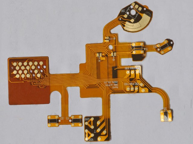
Flexible printed circuits (FPCs) are thin, flexible circuits made from polyimide or other polymer films with conductive traces etched or printed on them. FPCs allow connections between electronic components and devices where rigid printed circuit boards would be impractical. They are commonly used in consumer electronics, medical devices, automotive electronics, and other applications where flexibility, space savings, or durability are required.
Some key advantages of FPCs include:
- Flexibility – can be bent, folded or twisted to fit constrained spaces
- Thin and lightweight – takes up less space than rigid boards
- Durable – withstands vibration, shock and flexing
- Simple assembly – components can be soldered directly to traces
- Design freedom – can be shaped around components or devices
- High routing density – traces can be packed tightly for compact layouts
FPCs are made up of a base polyimide film layer, conductive copper traces, coverlay/solder mask, and stiffeners. Connectors, components, or devices are soldered to contact pads along the FPC. They can have one layer, two layers, or multilayers with traces sandwiching polyimide layers.
FPC Design Considerations
Several factors need to be considered when designing FPCs:
- Circuit density – Number of conductive layers and trace widths/spacings dictate component density. More layers allow higher density.
- Flexibility – Polyimide thickness, stiffeners, and minimum bend radii determine flex capability. Thinner polyimide and fewer stiffeners increase flexibility.
- Environment – FPC material selections must match expected temperature, chemical, UV, and other environmental conditions.
- Termination – FPC-to-board connections require compatible connectors or solder pads.
- Production volume – Higher volumes warrant investments in photolithographic processes for finer features.
- Testing – FPC circuits require specialized fixtures for reliable testing.
Careful FPC design results in optimal performance, reliability, and manufacturability.
FPC Manufacturing Process
FPC fabrication involves many steps to transform raw materials into finished circuits. Here is an overview of the key FPC manufacturing processes:
Base Layer Preparation
- Polyimide film blanks are selected to meet thickness, tolerance, and flexural endurance requirements.
- Adhesion promoters are applied to the polyimide surface to improve copper bonding.
- Photoimageable coverlay films are laminated onto one or both sides.
Conductive Patterning
- Copper foil is laminated onto the base layer.
- Photoresist is applied on the copper layers and patterned by photolithography.
- Etching removes unwanted copper, leaving behind desired conductive traces/pads.
- Resist is stripped away.
Final Processing
- Exposed copper is coated with solder mask for oxidation resistance.
- Stiffeners, connectors, or components are attached with adhesive.
- Electrical testing checks for defects.
- Circuits are separated from panels by routing.
- Completed FPCs are packaged for shipping.
Proper process controls during manufacturing ensure FPC quality and reliability.
Flexible Printed Circuit Assembly
Assembling components onto FPCs involves soldering surface mount devices (SMDs) and connectors onto contact pads. Several techniques are used:
Solder Paste Printing
- Solder paste is printed or dispensed onto FPC pads.
- Components are precisely placed onto pads using pick-and-place machines.
- Reflow soldering melts the paste, forming solder joints.
Connector Attachment
- Mechanical connectors are aligned to FPC contact areas.
- Reflow soldering, conductive adhesive, or insulation displacement forms connections.
Post-Assembly Processing
- Cleaning removes solder flux residue from assemblies.
- Conformal coating protects against environmental contamination.
- Visual inspection and testing verify assembly quality.
FPC assembly challenges include:
- Thin, flexible boards are harder to handle than rigid PCBs.
- Small component sizes and pitches require precision placement.
- Soldering processes must avoid damaging FPCs with excessive heat.
- Wraparound copper traces complicate solder masking.
- Warping can occur with uneven heating or cooling.
Automated assembly equipment developed for FPC manufacturing helps overcome these challenges.
FPC Assembly Equipment
Specialized equipment is used for handling, placing, and soldering components onto flexible circuits:
- Magazines – Hold FPCs in stack and feed into other tools. Manage warpage.
- Cutting/separating – Cut individual FPCs from panel accurately.
- Alignment systems – Precisely align FPCs for pick-and-place steps. Vacuum hold-down.
- Sprocketed conveyors – Transport FPC reel-to-reel with precise positioning.
- Placement heads – High precision pick-and-place for microcomponents. Multi-nozzle heads.
- Reflow ovens – Provide controlled heat profiles for lead-free soldering. Flexible heating zones.
- Cleaning – Clean flux residues without damaging FPCs.
- Inspection – Automated optical inspection looks for defects.
- Testing – Flying probe testers check circuits electrically.
The right assembly equipment enables efficient, high-yield FPC component placement and soldering.
FPC Assembly Challenges
Some key challenges involved in assembling components onto flexible PCBs include:
Warping and Wrinkling
As FPCs heat and cool during soldering, the differences in thermal expansion across material layers causes warping and wrinkling. This can displace components from their intended positions and cause defects. Warpage must be minimized by controlling thermal profiles and interfaces.
Registration
Achieving accurate component placement requires keeping FPCs properly registered and stable through conveyance, cutting, and loading steps. Automated alignment systems are essential.
Small Components
As devices shrink, assembling 0201 and 01005 chip components drives toward finer pitch sizes below 200 microns. High precision pick-and-place equipment is required.
Solder Masking
Applying solder mask to wrap copper traces on the edges of FPCs can be difficult compared to traditional solder masking on rigid boards. Specialized application methods may be needed.
Soldering Profiles
FPCs are more sensitive to heat stress than rigid boards. Reflow ovens must be tightly controlled to avoid overheating while still achieving good solder joint formation.
Inspection and Testing
Validating assembled FPCs requires inspection tools that can flex circuits and testing fixtures that make reliable contact with traces. Handling during imaging and probing also becomes more difficult.
By understanding these potential issues and selecting proper assembly processes, equipment, and materials, manufacturers can reliably assemble FPCs with maximum yields.
Trends in Flexible Printed Circuits
Some emerging trends that are shaping flexible PCB technology and applications include:
Miniaturization
FPCs integrate well with miniaturized surface mount devices, enabling smaller and thinner electronics. Traces under 25 microns accommodate finely pitched ICs.
High Density Interconnects
HDI FPC manufacturing utilizes lasers, plasma etching, and build-up processes to achieve multilevel circuits with microvias. This supports high density layouts.
Stretchable Circuits
Stretchable conductive polymers and serpentine circuit geometries create FPCs that can expand and contract. This brings new possibilities for wearable and biointegrated devices.
3D Printing
Additive manufacturing techniques like inkjet and aerosol printing can deposit conductive traces onto polymer substrates, opening new FPC prototyping and manufacturing methods.
Embedding Passives
Printing or integrating passive components like resistors and capacitors directly into an FPC layer saves space and simplifies assembly compared to discrete passives.
Flex-Rigid
Combining rigid sections (for connectors) with flexible regions on the same circuit broadens capabilities for applications with complex geometries and packaging.
Conclusion
Flexible printed circuits continue to grow in capability and adoption across many industries. With their thin profile, flexibility, durability, and design freedom, FPCs enable electronic devices and systems that are compact, lightweight, and innovative. Advances in materials, fabrication methods, and assembly processes allow FPCs to accommodate more functions in less space. By understanding the manufacturing steps, assembly techniques, equipment choices, and emerging trends, engineers can leverage flexible circuits to their fullest potential for the next generation of electronic products.
FQA
What are the main advantages of using flexible printed circuits versus rigid boards?
Some of the key advantages of FPCs over rigid boards are their flexibility, thinness, durability, design freedom, and high circuit density. FPCs can fit into tight spaces, withstand bending and vibration, and integrate closely with components through direct soldering.
What types of connectors are commonly used with flexible circuits?
Common connectors for flexible circuits include:
- Pressure contacts – Zebra strips, elastomeric
- Crimped contacts – Pierced insulation displacement
- Soldered – Reflow or hand soldering
- Adhesive – Anisotropic conductive films
- Compression – Pogo pins, spring probes
The connector style depends on the application requirements.
What are some key considerations when selecting FPC materials?
Important considerations for FPC materials include:
- Polyimide thickness and flexural properties
- Copper thickness and minimum trace spacing
- Dielectric constant and loss tangent of adhesives
- Glass transition temperature of layers
- Flammability rating
- Resistance to expected environmental conditions
How are components kept in position on FPCs during soldering?
Components are held in place on FPCs prior to soldering using solder paste tackiness, vacuum plates, specialized clamping fixtures, adhesive tapes, registration holes, or dedicated carrier plates beneath the FPC. This prevents movement during reflow.
How are very small chip components handled for flexible circuit assembly?
Precise flexible circuit assembly of microcomponents like 0201 and 01005 chips requires specialized high accuracy pick-and-place equipment. Nozzle designs, vision alignment, and handling processes are optimized for the small sizes. Vibration control and static reduction are also critical.


Leave a Reply