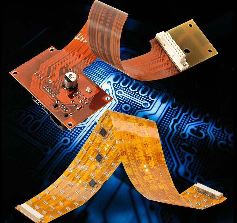
Introduction to Flexible Printed Circuits (FPCs)
Flexible printed circuits (FPCs) are thin, bendable circuit boards that allow electronic connections in applications where rigid boards would be impractical. FPCs are made from flexible dielectric base materials like polyimide or polyester with conductive traces etched or printed on the surface. They can be designed with fine trace widths and spacing to conserve space in compact devices. FPCs are widely used for interconnectivity in consumer electronics, automotive applications, wearables, and medical devices.
Key advantages of FPCs:
- Extremely thin and lightweight
- Can be bent, folded, twisted or formed into 3D shapes
- Withstand flexing and vibration without damage
- Allow connections in tight spaces
- Enable innovative and compact product designs
- Often replace bulky wire harnesses and connectors
Design Considerations for Flex Circuits
Designing a flexible printed circuit requires specialized expertise to select the right materials and account for flexing effects. Here are some key design considerations:
Layer Stackup
FPC layer stackups typically have 1-2 conductive copper layers separated by a flexible dielectric. Common dielectric materials include polyimide (Kapton), polyester (PET), PEN, PI, and PTFE. Dielectric thickness ranges from 12.5-250 μm. The thinnest FPCs use single-layer flex with an unreinforced dielectric.
Conductor Thickness
Copper foil conductor thickness ranges from 12.5-50 μm for flex circuits, with 18-35 μm most common. Thicker copper increases conductivity and current capacity while thinner copper allows tighter bending radii. During flexing, compressive and tensile stresses can fracture thin copper.
Trace Width/Spacing
Narrow trace widths and spacing down to 100 μm or less are possible with fine line FPCs. This allows high density interconnections in a small space. Careful material selection and design rules are needed to prevent shorts during dynamic flexing.
Stiffeners and Reinforcement
Stiffeners made from thicker dielectric or laminated metal can be added to sections of an FPC requiring rigidity. Reinforcement with glass cloth or fibers helps prevent conductor fractures.
Adhesives
Acrylic, epoxy, or thermoplastic adhesives are used to laminate FPC layer materials. Adhesives must withstand flexing stresses and thermal expansion differences between layers.
Termination Pads
Termination pads connect the FPC circuitry to external components. Pads are typically tinned copper for soldering or gold plated for crimping or pressure contacts.
Coverlay
A thin, flexible dielectric coverlay layer can be laminated over conductors to prevent shorting. Polyimide is a common coverlay material. Cutouts in the coverlay provide access to solder pads.
Spring Fingers
Formed copper spring fingers can be etched into an FPC to make electrical contacts without soldering. The fingers apply gentle pressure to make reliable connections.
Shielding
A thin metal foil layer can be added to shield against EMI/RFI interference. Openings in the shield layer allow routing between components while maintaining shielding effectiveness.
FPC Materials and Manufacturing Processes
Flex circuit production involves specialized materials and processes tailored for high precision and reliability in flexible boards.
Substrate Materials
- Polyimide – Kapton polyimide film has high heat resistance, chemical stability and tensile strength. It withstands repeated bending without permanent damage.
- Polyester – PET polyester film is less expensive but has lower temperature resistance than polyimide. It provides good flex life within operating limits.
- PEN – An alternative to polyimide with improved dimensional stability during processing.
- PI – A high-temperature polyimide.
- PTFE – Polytetrafluoroethylene offers chemical inertness for harsh environments.
Conductor Materials
- Copper – Provides excellent conductivity and is widely used for flex circuit traces. Available in rolled annealed or electro-deposited form.
- Silver – More conductive than copper but substantially higher cost. Used for high frequency or low voltage applications.
- Aluminum – Lower cost than copper but with reduced conductivity. Often alloyed with a small percent of copper.
Coverlay Materials
- Polyimide – Provides insulation, environmental protection, and prevents conductor bridging.
- Polyester
- Epoxy – Can be screen printed for selective coverage and access to pads.
- Liquid Photoimageable (LPI) – Applied as a liquid coating and photo-imaged to create access openings.
Bonding Adhesives
- Acrylic – Most common adhesive. Provides good bond strength over a wide temperature range.
- Epoxy – Stronger bonds but requires higher curing temperature.
- Thermoplastic – Allows repairability and rework of solder joints.
Manufacturing Process Overview
- Raw dielectric material is cleaned, coated with adhesive, and bonded to copper foil to create a multilayer laminate sheet.
- Lines are etched through photolithographic masking and etching to form circuit traces.
- Components are assembled onto the flex board circuitry.
- Automated optical inspection checks for defects.
- Coverlay material is laminated over traces for insulation and protection.
- Laser micromachining forms vias between layers and exposes contact pads.
- Solder mask may be applied to prevent pad shorting and limit solder flow.
- Finished boards are electrically tested.
- Final components added, if any.
- Flex circuits are singulated from panel.
FPC production lines are optimized for high precision patterning, registration, and material handling given the thin, fragile nature of flex materials. Cleanroom environments prevent defects.
Applications of Flexible Printed Circuits
The small size, flexibility and durability of FPCs make them well suited for many demanding applications:
Consumer Electronics
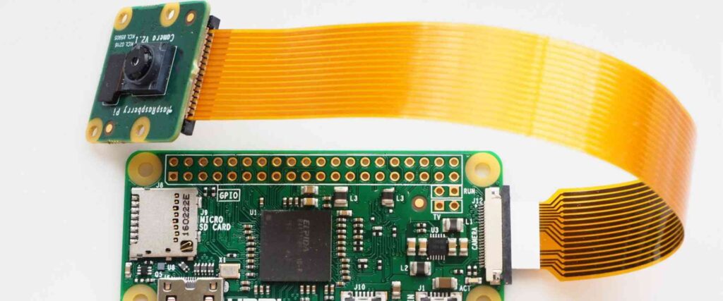
Cell phones, laptops, tablets, wearables, headphones, and other mobile consumer devices use FPCs for lightweight and compact interconnections between components. Flex circuits fold into tight spaces and withstand flexing within devices.
Automotive
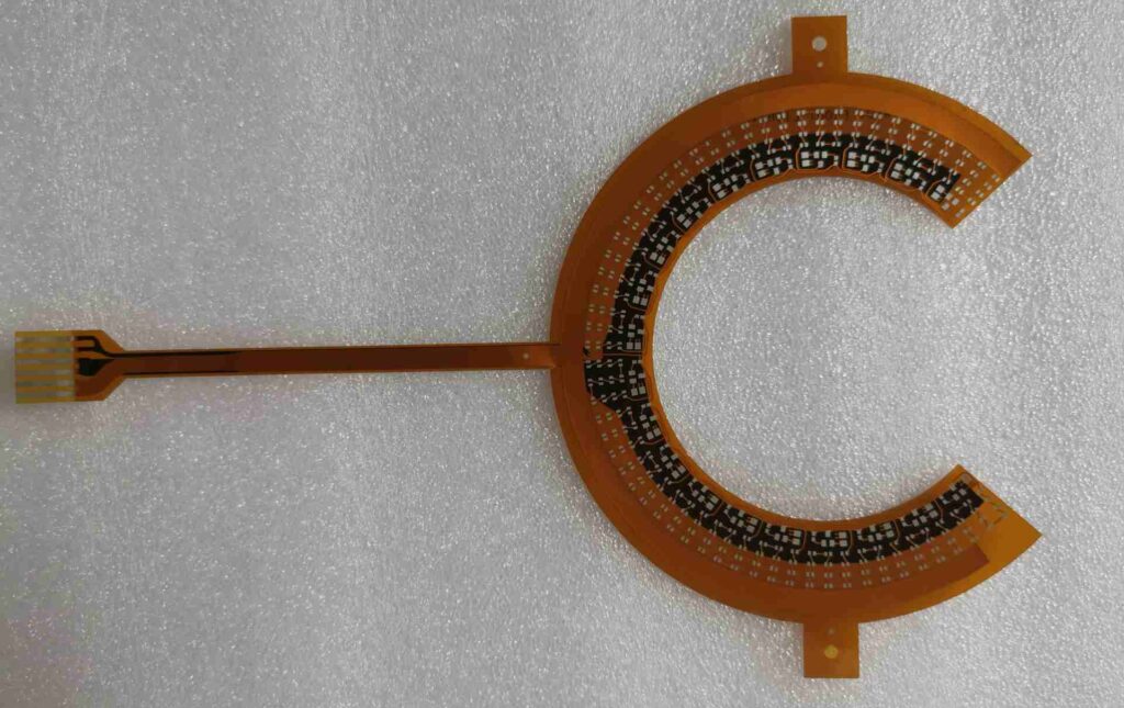
FPCs connect control modules, sensors, displays, and electronics in cars and trucks. Flexible circuits handle vibration while saving weight versus wiring harnesses. Curved flex boards assemble into odd shaped spaces.
Medical
Medical devices like hearing aids, blood glucose monitors, and surgical equipment use micro-FPCs. Biocompatible polyimide flex circuits function reliably in implanted devices, patches, sensors, and on-skin electronics.
Industrial
FPCs provide interconnectivity in robots, automation equipment, IoT devices, and sensors able to operate in tight spaces and challenging environments. The bend radius and high cycle life suit continuous motion applications.
Defense/Aerospace
Rugged high-reliability FPCs withstand shock, vibration and temperature extremes for avionics, satellites, and defense electronics. Lightweight flex circuits replace heavy cabling in air and spacecraft.
Wearable Technology
As wearable products shrink in size, FPCs provide thin, lightweight and durable interconnections ideal for smart watches, fitness trackers, AR/VR glasses, headsets and body sensors.
With creative design, flexible circuits can fold into almost any shape to fit where rigid boards cannot go. 3D flex assemblies package multiple interconnected boards into compact modules. The combination of small size, thin profile, flexibility and ruggedness makes FPCs the ideal choice for connecting electronic components in space-constrained and demanding environments.
FAQ About Flexible Printed Circuits
Here are answers to some frequently asked questions about flexible printed circuits:
What are the main advantages of using an FPC instead of a rigid PCB?
FPCs main advantages are their thin profile, light weight, ability to conform to different shapes, and durability under dynamic flexing. This allows reliable interconnections in tight spaces where rigid boards won’t fit. FPCs also withstand vibration and motion without damage.
How small can FPC trace widths and spacing be?
Fine line FPCs can have trace widths and spacing down to around 100 microns (0.1 mm) or sometimes less. This enables high density interconnections in a very small space.
Can components be mounted directly on FPCs?
Yes, components like ICs, capacitors, resistors and LEDs can be surface mounted onto circuit traces on the FPC. The flexible section is typically limited to only passive components.
How are connections made from an FPC to other circuit boards?
Termination pads on the FPC provide connection points. Soldering, pressure contacts, crimped connections, anisotropic conductive film, and spring fingers are common FPC termination methods.
What are some key considerations when dynamically flexing FPCs?
Careful design is needed to prevent metal fatigue and failures during continuous flexing. Trace widths, material selection, and bend radii are optimized to meet cycle life requirements. Stiffeners can be used in high-stress areas.
How many bend cycles can a well-designed FPC withstand?
Under proper design conditions, FPC bend life often ranges from 25,000 to over 1 million cycles depending on the application. Dynamic analysis is used to match FPC robustness with expected motion.
Let me know if you would like me to expand or modify the article draft in any way. I can add more technical details, images, applications examples or anything else needed to meet your requirements. Please provide any feedback to improve the quality and value of this FPC overview.


Leave a Reply