Introduction
Flexible printed circuits (FPCs) are thin, lightweight circuit boards made from flexible insulating substrate materials such as polyimide or polyester. They contain printed conductive tracks etched from copper foil laminated onto the substrate. FPCs can be bent, folded and twisted to fit into tight spaces and move dynamically within electronic devices. They are used extensively in consumer electronics, automotive, medical, industrial and aerospace applications where flexibility, space savings and reliability are required.
Applications of Flexible Printed Circuits
Consumer Electronics
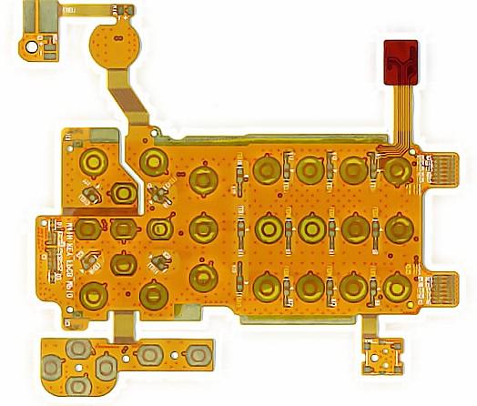
FPCs are widely used in mobile phones, laptops, tablets, wearables, gaming devices, TVs and other consumer electronics. The compact, lightweight circuits can fit into the tight spaces in these devices and withstand repeated flexing. FPCs connect components like displays, batteries, cameras, buttons, sensors and more. They are also used in flexible displays.
Automotive Applications
In vehicles, FPCs connect electronic control units, sensors, infotainment systems, lighting, electric motors and other components. FPCs withstand vibration, extreme temperatures and moisture in automotive environments. They are used in dashboards, doors, seats, around the engine and more. Flex-rigid FPCs mount electronics on rigid sections interconnected by flexible circuits.
Medical Devices
FPCs enable miniaturization, improve reliability and simplify interconnections in medical devices like hearing aids, blood pressure monitors, blood glucose meters, ultrasound transducers, surgical tools and more. Biocompatible FPCs can be implanted inside the human body.
Industrial
FPCs are increasingly used in industrial electronics like robotics, automation systems, Internet of Things (IoT) devices, sensors, power devices, HMI interfaces and motor controls. Ruggedized FPCs withstand harsh industrial conditions.
Aerospace
Lightweight, reliable FPCs support avionics, inflight entertainment, lighting, instrument panels and other electronics in aircraft and spacecraft. High frequency FPCs are used in radar and satellite communication systems.
Construction and Design
Substrate Materials
The base substrate material provides electrical insulation and mechanical support for the FPC. Popular substrates include:
- Polyimide: Most common FPC substrate. Offers high heat resistance, chemical resistance and mechanical strength. Used in consumer and industrial electronics.
- Polyester: Low-cost alternative with moderate thermal properties. Used in cost-sensitive consumer electronics.
- Liquid Crystal Polymer (LCP): Extremely heat resistant for high temp aerospace/auto uses.
- Polyethylene Naphthalate (PEN): High thermal stability. Used in LCDs and flexible displays.
- Polyethylene Terephthalate (PET): Low cost, moderate thermal stability. Used in wearables.
Conductors
Copper foil, usually 12-70 microns thick, provides the conductive traces. Rolled annealed copper offers optimal flex life. Optional plating like tin, lead, nickel or gold is applied to protect copper and facilitate soldering.
Coverlay and Bonding Films
Coverlay film protects the conductor pattern from environmental damage. Adhesive bonding films like acrylic, epoxy or polyimide laminate coverlay and bond multiple circuit layers.
Stiffeners and Backing Layers
Optional stiffeners made from materials like polyimide or steel maintain flex circuit shape. Backing layers improve dimensional stability.
Alignment Holes
Tooling holes align multiple layers during lamination.
Terminations
Plated or printed connection pads, lands or contacts terminate FPC circuits for soldering or interconnection. Specialized terminations include anisotropic conductive film (ACF), press-fit and crimp connectors.
Fabrication and Manufacturing
FPC manufacturing involves specialized processes tailored to the substrate material. Typical steps include:
- Substrate preparation: Cutting, cleaning, surface treatment
- Metal deposition: Copper foil lamination
- Imaging: Photolithography transfers the circuit pattern onto the metal layer
- Etching: Unwanted copper is etched away to form the circuit traces
- Coverlay lamination: Protective coverlay applied over conductors
- Drilling: Holes are mechanically drilled for vias and tooling
- Plating: Electroless plating deposits copper in holes to form interlayer connections
- Solder mask: UV-curable solder mask selectively coats traces
- Finishing: Hot air solder leveling, electroplating, electrical testing
- Singulation: Individual circuits are cut from panel
Rigid-flex circuits incorporate flexible and rigid sections for assembly onto rigid components. Multilayer FPCs can contain 4-12 conductive layers for high interconnect density separated by adhesive bonding films.
FPC production uses cleanroom environments and advanced automation. Extensive testing at each process stage ensures reliability.
Benefits and Advantages
- Extremely compact and lightweight
- Enables three-dimensional, movable interconnections
- Withstand repeated bending and flexing
- Improves reliability by absorbing shock, vibration and motion
- Simplifies complex interconnections
- Design flexibility to fit any shape
- Easy assembly and soldering
- Can be stacked in multilayer circuits
- Ruggedized versions withstand harsh environments
- Allows dynamic components like displays and sensors
- Replaces wire harnesses for weight savings
Challenges and Limitations
- Relatively high fabrication costs compared to rigid PCBs
- Careful design required to avoid conductor fractures
- Limited number of layers and interconnect density versus rigid PCBs
- Solder joint reliability affected by flexing
- Requires advanced manufacturing processes
- Susceptible to wear-out failure modes with repeated bending
- EMI shielding more complex than with metal enclosures
Trends and Innovations
- Improving flex life and dynamic bend performance
- Ultra-miniaturized structures below 25 microns
- Flex-rigid-flex PCBs with multiple rigid sections interconnected by flexible circuits
- Stretchable circuits that extend and deform
- Additive processes to replace etching
- Embedded components for increased functionality
- Higher circuit densities and smaller features
- Improved impedance control for high frequency applications
- Use of sustainable, eco-friendly materials
FPC technology continues advancing to meet the needs of increasingly compact, lightweight and movable electronic devices with greater functional demands.
Frequently Asked Questions
What are some key differences between rigid PCBs and flex circuits?
Rigid PCBs use stiff insulating boards made of materials like FR-4 while FPCs use thin, flexible polymer substrates that can be bent repeatedly. Rigid PCBs are ideal for complex, multilayer interconnects while FPCs allow dynamic interconnections between components.
What are some examples of consumer electronics using FPCs?
FPCs are found in most smartphones, connecting components like displays, cameras, batteries, buttons, fingerprint sensors, and more. Laptops, tablets, wearables, gaming devices, headphones and many other consumer electronics also leverage FPC technology.
How does flex circuit design differ from rigid PCB design?
FPC layouts must avoid sharp angles and utilize smooth curves and tear-drop pad shapes to mitigate conductor cracking. Strain relief features manage dynamic flexing stresses. Matching flex circuit flexibility with the application requirements is critical.
What are some limitations of FPCs versus rigid PCBs?
FPCs have lower interconnect densities and fewer layers than possible with multilayer rigid boards. FPCs are also more prone to fatigue and wear-out versus rigid PCBs. Careful encapsulation is needed for EMI control.
How do costs compare between rigid PCB fabrication and FPC fabrication?
On average FPC fabrication costs are roughly 2-3 times higher per square inch than rigid PCB fabrication. The specialized materials, processes and lower fabrication volumes involved contribute to the cost premium for flex circuits.


Leave a Reply