Introduction
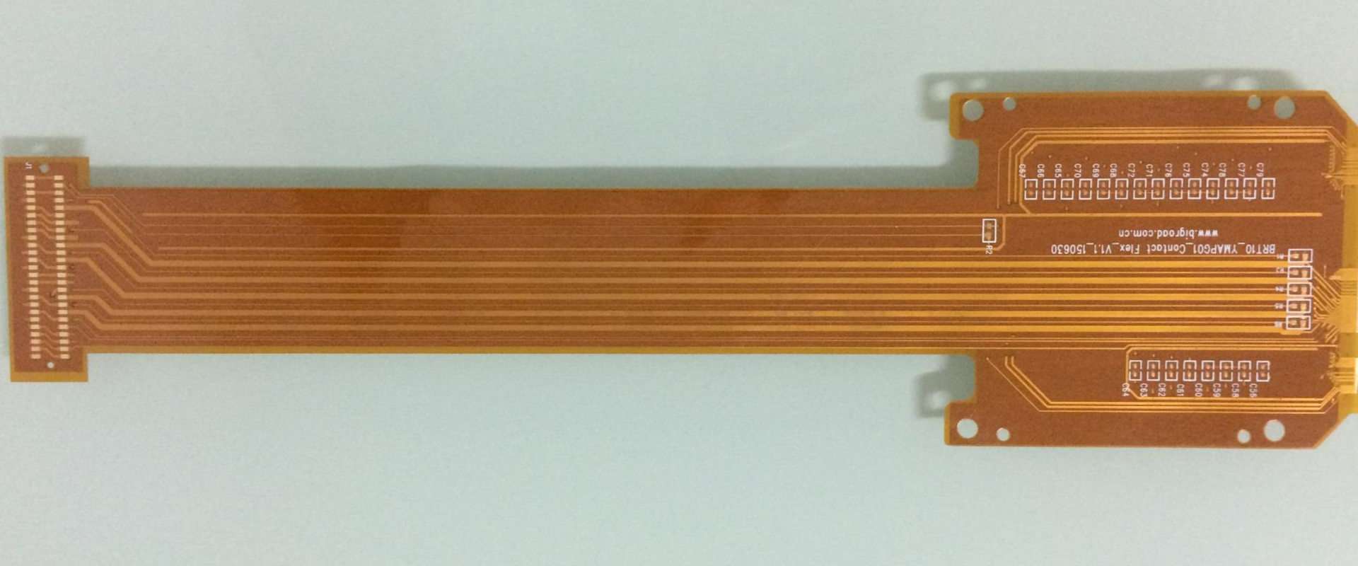
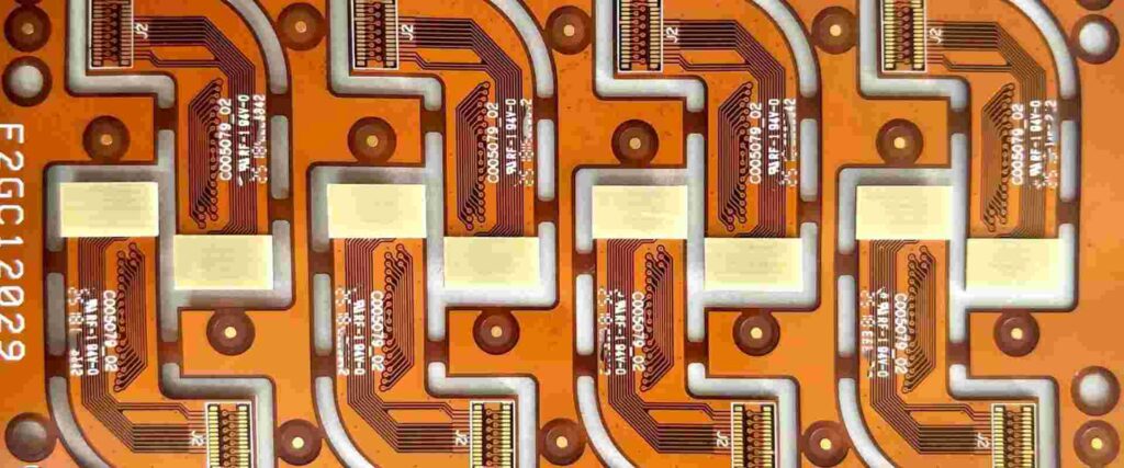
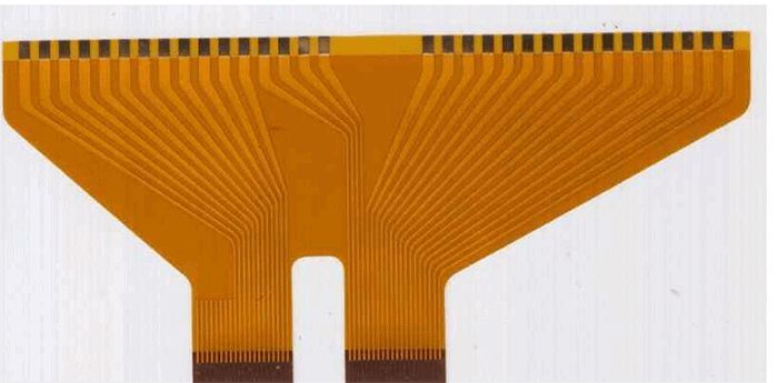
Flexible printed circuit boards (flex PCBs) are a type of printed circuit board made from flexible materials like polyimide that can bend and flex. Flex PCBs allow connections between electronics in applications where rigid boards would be impractical. They are commonly used in consumer electronics, medical devices, aerospace applications, and more.
Soldering flex PCBs requires some specialized techniques compared to soldering rigid boards. The flexible nature of the boards means you have to take measures to prevent damaging the boards during soldering. Proper flex PCB soldering relies on using the right materials and methods.
This guide will cover everything you need to know about soldering flex PCBs. We’ll discuss:
- Flex PCB soldering challenges
- Recommended materials and tools
- Soldering techniques and best practices
- Inspection and testing
- Troubleshooting soldering issues
Follow these flex PCB soldering guidelines and you’ll be able to work with flex circuits effectively. Let’s get started!
Challenges of Flex PCB Soldering
Soldering flexible PCBs comes with some unique challenges not found when working with rigid boards:
Flexing and Bending
The flexible nature of the boards means they can bend and flex during soldering. This can make soldering difficult if the board is not properly supported. Flexing can also lead to cracked joints over time.
Heat Sensitivity
Most flex PCB materials are sensitive to high heat. Too much heat can damage the flexible substrate, delaminate layers, or burn the boards.
Small Features and Spaces
Flex PCBs often have very small features and spaces between conductors. This requires precision soldering methods.
Limited Component Options
Component options are more limited compared to rigid PCBs. Components must be able to withstand flexing.
Difficult Inspection
It can be difficult to inspect solder joints and connections on flex circuits once assembled due to the flexible, layered construction.
Recommended Materials and Tools
To address the challenges of flex PCB soldering, you need the right materials and tools:
Solder Paste
Use solder paste designed for flex PCB assembly, like Chip Quik SMD291AX10. The flux chemistry is optimized to prevent charring the flexible substrate during reflow.
Solder Wire
For hand soldering, use a no-clean solder wire in the smallest gauge possible for the application. 0.010″ to 0.015″ diameter is common. This limits heat transfer to the board.
Soldering Iron
Use a temperature controlled soldering iron with a fine tip. Common tip sizes for flex PCB work range from 0.01″ to 0.025″. A tip around 1mm is a good general purpose size.
Soldering Tweezers
Soldering tweezers allow precise application of heat. They are useful for rework of small SMT components.
Flux
Liquid flux is essential for flex PCB soldering to prevent oxidation and improve solder flow. Use a no-clean flux designed for flex circuit assembly.
Support Fixture
Some type of support fixture is necessary to prevent the board from excessive bending during soldering. Things like rigid support bars and vacuum hold-down tools can be used.
Microscope
An inspection microscope aids precise soldering and inspection of joints. Stereo zoom microscopes in the 10-50X magnification range are ideal.
Multimeter
A digital multimeter allows basic connectivity testing and troubleshooting of the flex circuit.
Flex PCB Soldering Techniques
With the right tools in hand, you can move on to the actual soldering process. Here are some best practices to follow:
Prepare the Board
- Clean the board with isopropyl alcohol to remove any contaminants left from fabrication.
- Use solder mask in areas around pads to limit solder spreading across conductors.
- Cover unused connector pads with Kapton tape to prevent solder leaching.
- Apply liquid flux to all surfaces to be soldered. Reapply flux regularly during extended soldering.
Manage Heat
- Keep the soldering iron tip clean and set to an appropriate temperature for the board materials, usually 650-700°F (345-370°C).
- Use the lowest temperature necessary to melt the solder.
- Limit contact between the iron tip and the board to prevent overheating.
- Allow adequate cool down time between solder joints.
- Use a heat sink, like a crocodile clip, when soldering near heat-sensitive components.
Support the Board
- Use a rigid support under the board near the solder area to prevent bending and flexing.
- For overall board support, lay the PCB on a soft surface like foam or rubber. Do not allow the board to hang off the edges.
- Vacuum hold-down tools can securely support boards during reflow soldering in an oven.
Apply Solder
- Use solder wire, solder paste, or preforms matched to the size of the pads.
- Apply only as much solder as needed for the joint – avoid blobbing solder on top of pads.
- For surface-mount work, use a thin layer of solder paste deposited precisely on the pads.
- When hand soldering wires, use the minimum heat needed to flow the solder. Avoid moving the wire until the solder has cooled.
Inspect Joints
- Visually inspect each solder joint under magnification. Look for proper wetting, fillet formation, and alignment.
- Conduct connectivity tests after every few solder joints to catch problems early.
- X-ray inspection can reveal hidden flaws like cold solder joints.
Flex PCB Soldering Inspection and Testing
Thorough inspection and testing ensures quality soldering and a properly working flex assembly. Here are recommended procedures:
Visual Inspection
Visually check every solder joint under a microscope. Look for:
- Proper wetting and spreading across pad and component lead
- Shiny solder fillet formation indicates good wetting
- No visible cracks or holes in solder joint
- Component alignment – component should be flat and aligned properly
Compare to an example of a good joint if needed.
Connectivity Testing
Use a multimeter to test conductivity across every joint and connection:
- Test pad-to-pad connections by probing along traces.
- Verify connections from integrated circuits pins to solder pads.
- Ensure cables and wires have continuity through the joint.
Check the board layer-by-layer if needed. Test before and after flexing the board.
Automated Inspection
Automated optical inspection (AOI) and x-ray provide detailed analysis:
- AOI can quickly scan joints and identify problems difficult to see under a microscope.
- X-ray reveals hidden flaws like cold solder joints deep in BGA packages.
Circuit Function Tests
Run full functional tests of the board after soldering:
- Load firmware/software and validate basic functions.
- Stress test by flexing the board continuously while powered on. All circuits should perform reliably.
Thorough testing verifies the board can withstand its intended environment.
Documentation
Document all inspection and testing. Include:
- Microscope images of sample good/bad solder joints
- Connectivity test data
- AOI/x-ray defect analysis
- Details of circuit functionality testing
- Any rework/repairs performed
Documentation provides quality records and aids future troubleshooting.
Troubleshooting Flex PCB Soldering Issues
Despite best efforts, you may encounter some issues during flex PCB soldering:
Solder Beading
Solder forms a bead on the pad instead of wetting and spreading out.
- Cause: Insufficient flux or surface contamination.
- Solution: Clean pad thoroughly and apply liquid flux before soldering.
Cold Solder Joint
Joint looks shiny but has poor adhesion to the pad/lead.
- Cause: Joint moved before solder cooled. Low iron temperature.
- Solution: Hold parts still while solder cools. Increase iron temperature slightly.
Cracked Joint
Solder joint develops small cracks, often radiating from the pad corner.
- Cause: Board flexing during soldering. Thermal cycling fatigue over time.
- Solution: Support board near solder area. Stress relief connection points.
Overheated Board
Evidence of heat damage to the board substrate and traces.
- Cause: Excessive heat during soldering.
- Solution: Reduce iron temperature, limit contact time, and allow cooling between joints.
With careful process controls and inspection, you can avoid most flex PCB soldering defects and create reliable, high-quality solder joints.
FQA
What are the main challenges of soldering flex PCBs?
The main challenges are:
- Flexing and bending of the board during soldering
- Heat sensitivity of flexible substrate materials
- Small spaces and features on the PCB
- Limited component options compatible with flexing
- Difficult inspection of solder joints after assembly
What type of soldering iron tip is best for flex PCBs?
Use a fine tip soldering iron between 0.01″ – 0.025″ diameter. The small tip concentrates heat for soldering while limiting heat transfer into the flexible board. A temperature controlled iron will maintain the set temperature precisely.
How can I prevent damage from excessive heat when soldering?
- Use the lowest soldering iron temperature to melt the solder.
- Limit contact between the iron tip and the board.
- Allow adequate cooling time between solder joints.
- Use heat sinks to protect sensitive components.
- Choose heat-resistant PCB materials like polyimide.
What is the benefit of liquid flux in flex PCB soldering?
Liquid flux removes surface oxidation and contaminants, allowing the molten solder to properly wet and spread on the metal surfaces to be joined. Flux improves solder flow and strengthens the joint. No-clean flex PCB fluxes prevent charring at high temperatures. Reapply flux regularly during soldering.
How can I ensure reliable connections when soldering flex cables?
- Use the smallest solder wire gauge possible to limit heat transfer
- Apply only enough solder to make the joint – avoid blobbing
- Support both sides of the joint to prevent flexing
- Let the joint cool fully before moving the cable
- Stress relieve the joint with heat shrink tubing
Summary
This covers the complete process of soldering flexible printed circuit boards. The unique properties of flex PCBs present some challenges that must be addressed through proper materials, support fixtures, controlled heat, precision soldering, inspection, and testing. Following the guidelines provided here will help you reliably solder flex circuits boards and avoid common defects. Let me know if you have any other flex PCB soldering questions!


Leave a Reply