Introduction to Flex Circuits
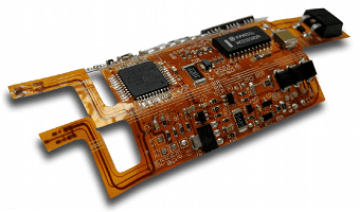
Flexible printed circuit boards (flex PCBs or flex circuits) are a type of printed circuit board that is made with flexible dielectric materials such as polyimide or polyester. This allows the board to flex and bend to fit into tight or moving spaces in electronic devices. Flex circuits can be single-sided, double-sided, or multilayer, with conductors etched from copper foil onto the flexible base material.
Flex PCBs were first designed in the mid-1950s for use in aerospace applications. Today they are widely used in consumer electronics, medical devices, industrial equipment, and more. Below are some of the key benefits that make flex circuits a good choice for many applications:
- Flexible – Can be bent, folded, or wrapped to fit constrained spaces
- Lightweight – Weigh less than rigid boards
- Thin and customizable – Can be made thinner than 0.001 inches
- Durable – Can withstand vibration, shock, and repeated flexing
- Reliable connections – Excellent for dynamic or high-motion applications
- Design freedom – Can take any shape, size or layout
Some common applications of flex PCBs include:
- Wearable devices
- Medical devices
- Robotics and UAVs
- Automotive electronics
- Consumer electronics
- Industrial and IoT devices
- Military and aerospace systems
Flex Circuit Materials
Flex circuits can be fabricated using many types of flexible insulating materials as the base substrate. Some common materials used are:
- Polyimide (Kapton) – Most widely used flex circuit substrate. Offers excellent thermal stability and chemical resistance.
- Polyester (PET) – Lower cost alternative to polyimide. Not as heat resistant.
- Polyethylene (PE) – Soft and flexible. Used for low temperature or single-use applications.
- Fluoropolymers (PTFE) – Excellent thermal and chemical resistance. Expensive.
- PeekTM – High temperature resistance and long-term reliability. Costly.
The conductive layers are typically made from rolled annealed copper foil, with a thickness from 1 oz (35 μm) down to 1⁄4 oz (8 μm) or thinner. The trend is to use thinner and thinner copper foils to allow more flexible and space-efficient flex circuits.
Flexible PCB Design Considerations
Designing a reliable flex PCB requires paying close attention to the planned application environments. Here are some important flex circuit design considerations:
Thermal Management
Since flex circuits use thin polymer substrates, they can be prone to overheating. Careful thermal analysis should be done, and steps taken to dissipate heat like:
- Use of thermal vias
- Addition of copper heat sinks/planes
- Incorporating space or openings for ventilation
- Selection of base materials like polyimide that resist thermal issues
Flexibility and Bend Radii
A key spec for flex PCBs is the minimum bend radius they can tolerate without damage. This depends on factors like:
- Thickness of the flex layers
- Copper weight (thicker copper is less flexible)
- Board material and reinforcement
- Location of bends relative to components
Typical minimum bend radii range from 2-10x the circuit thickness for dynamic or high flex applications.
Layer Count
Single, double, and multilayer flex configurations are possible. More layers allow higher circuit density but reduce flexibility. Rigid sections can be added for components and connectors.
Conductor Spacing and Routing
Trace widths and spacing must follow the flexible substrate manufacturer’s guidelines, which are typically more conservative than rigid PCBs. Wider spacing helps ensure conductors don’t crack on bends.
Stiffener Integration
Strategically placed stiffeners may be needed. This helps minimize flexing in certain areas and prevents damage. Stiffeners can be added by using thicker copper, bonding aluminum sheets, or adding protective covers.
Component Selection and Attachment
Choosing the right components is critical for reliable flex PCB performance. Lightweight SMT devices are commonly used. Through-hole parts can be specified, but will act as rigid sections. Stresses must be modeled to ensure robust connections. Components are typically attached via soldering or conductive epoxy.
Flexible PCB Assembly Processes
Building completed circuit assemblies with flex PCBs involves specialized assembly and integration processes. Here are some of the main process steps and considerations:
Solder Paste Printing
Applying solder paste to flex PCBs is done with stencil printing, but requires specialized techniques:
- Laser cut steel or nickle-plated stencils are typically used
- Fine feature printers are preferred for printing small features
- Low residue, no-clean solder pastes are recommended
- Enclosed print heads help contain any lifted pads during printing
- Vision alignment systems ensure accurate print placement
Component Placement
Flex circuits have tight component pitch, so automated pick-and-place systems are normally used. Key factors include:
- Vacuum nozzle sizes matched to small component sizes
- Pick-and-place accuracy and repeatability
- Gentle component handling to avoid flex circuit damage
- Vision systems to check placement accuracy
Reflow Soldering
Reflow soldering attachment requires specialized profiles and techniques:
- Short preheat stages to avoid warping the thin flex boards
- Precise thermal control to avoid overheating flex boards or components
- Supporting boards underneath when convection reflowing
- Potential use of vapor phase systems for gentle, uniform heating
Conformal Coating and Encapsulation
Applying protective coatings is often needed for durability, moisture and dust resistance. Options include:
- Acrylic, urethane, silicone and other coatings
- Selective coating with manual dispensing or jetting
- Underfilling components like BGAs for added strength
- Full enclosure with injection molded plastics
Post-Solder Cleaning
No-clean soldering processes are used whenever possible. For mission-critical systems with tight reliability requirements, post-solder cleaning may be needed:
- Aqueous cleaning agents or semi-aqueous with low-standoff components
- Cleaning agents designed for flex circuits to limit potential damage
- Gentle application of cleaning fluid (spray or immersion)
- Extra rinsing and drying steps to remove residues
Automated Optical Inspection
AOI systems are essential for verifying assembly quality and catching defects on flex circuits:
- Color cameras needed for inspecting shiny conductor surfaces
- High magnification and fine optics resolve small features
- Advanced signal processing for accurate analysis
- PROGRAMMED to check solder joints, coatings, placement, etc.
Rigid-Flex Assembly
Many flex designs incorporate standard rigid PCB sections. Unique steps for rigid-flex assembly include:
- Careful handling during layup to avoid rigid-flex interface separation
- Folding or bending following panelization guidelines
- Edge bonding at the rigid-flex junctions for added strength
- Precise techniques to minimize bowing or warpage
- Specialized fixtures, carriers and pallets to support assembly
Testing and Inspection
Thorough testing ensures flex circuit reliability:
- In-circuit testers confirm electrical connectivity
- Flying probe testers perform bed-of-nails testing
- Functional testers validate system operation
- Burn-in testing screens for early life failures
- X-ray inspection detects hidden defects or damage
- Endoscopes visually inspect bends and complex areas
Key Flex PCB Assembly Challenges
While offering many benefits, assembling flex PCBs comes with some unique challenges:
- Working with thin, flimsy circuits requires careful handling
- Flex boards are prone to warping and twisting during assembly
- Fine features and tight component spacing increase production difficulties
- Bends and dynamic sections make assembly integration more complex
- Rework and repair is very difficult on fragile flex boards
- Flex materials can be more sensitive to assembly process conditions
- Dense cabling must be effectively managed in compact systems
With proper design considerations and advanced assembly processes, these hurdles can be cleared to build reliable, high-performance flex circuit assemblies.
Comparison of Rigid and Flexible PCB Technologies
| Property | Rigid PCB | Flex PCB |
|---|---|---|
| Materials | FR-4, CEM-1, ceramic, polyimide | Polyimide, polyester, polyethylene |
| Layer Count | Up to 30+ | Typically 1-6 |
| Thickness | 0.5mm to 5mm typically | Down to 0.05mm |
| Copper Weight | 1oz to 6oz typical | 0.5oz to 1oz |
| Minimum Bend Radius | None, rigid | 2 to 10 x circuit thickness |
| Design | Rectangular boards, some irregular shapes | Can take any 2D or 3D shape |
| Features and Spacing | Line width/space down to 4/4 mil | Fine features, tighter spacing |
| Components | Through-hole and SMT parts | Mainly SMT, some through-hole |
| Thermal Management | Vias, copper planes | Limited ability, high importance |
| Assembly Process | Soldering, press-fit, other | Requires specialized techniques |
| Main Applications | High-volume consumer electronics, telecommunications, industrial, medical | Compact, high-flex uses like wearables, aerospace |
Flex PCB Assembly FAQ
Here are answers to some frequently asked questions about flex PCB assembly:
Q: What are some typical applications for assembled flex circuits?
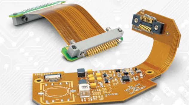
A: Flex assemblies are used extensively in compact devices like cell phones, medical tools, IoT wearables, robotics, drones, and aerospace systems. Their flexibility allows reliable interconnections in small, dynamic, or high-motion applications.
Q: How are components attached to flex PCBs?
A: SMT components are most often used, soldered via reflow or in some cases conductive epoxy. Through-hole parts can also be wave or selectively soldered but act as rigid sections. Careful modelling and testing is needed to ensure robust connections that won’t crack under bending and flexing.
Q: What are some key ways flex circuit assemblies are tested?
A: Testing ensures reliability and catches any defects. Methods include in-circuit testing, flying probe testing, x-ray inspection to reveal hidden flaws, burn-in testing for early failures, functional validation, and visual inspection of solder joints and bends using microscopes or endoscopes.
Q: Can flex PCBs incorporate standard rigid PCB sections?
A: Yes, many flex designs have integrated rigid sections usually at areas interfacing with connectors, heavier components, or for multilayer areas. Special handling during assembly and edge bonding at the rigid-flex junctions is important.
Q: How are components kept in place on flexible circuits during assembly?
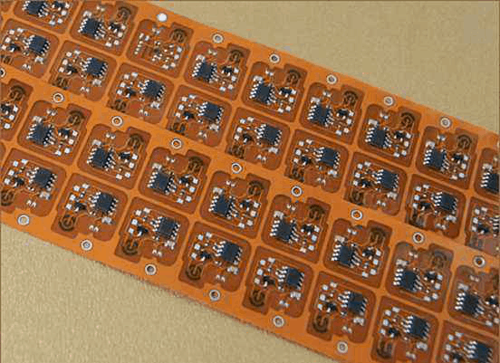
A: Support tooling, jigs, fixtures, and carriers are crucial. Tacky tapes, vacuum platens, and other fixturing help minimize flexing and control product handling. Flexible boards may be assembled in panels for stability and later depanelized. Careful process design and carrier engineering ensures reliable assembly.
In summary, flex PCBs enable creative and compact electronic designs but require adaptations to standard assembly processes. With thoughtful design and process planning, high-reliability and high-yield flex circuit assemblies can be manufactured successfully.


Leave a Reply