Introduction
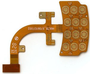
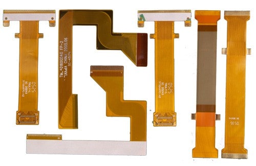
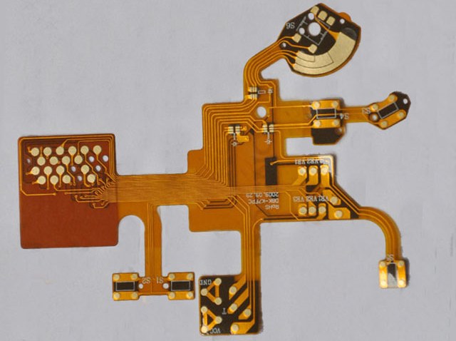
Flexible printed circuits (FPCs) have become an essential component in modern electronics due to their ability to bend and flex to fit within tight spaces. As flexible circuits continue to grow in popularity, manufacturers must understand the properties and applications of the various flexible circuit board materials available. This article will provide a comprehensive overview of the most common flexible PCB materials used today and discuss key considerations when selecting materials based on production needs and product specifications.
Polyimide Film

Polyimide (PI) film is one of the most widely used flexible circuit board materials. This thermosetting polymer has high heat resistance, chemical stability, and mechanical strength combined with electrical insulation properties. Some key properties of polyimide film include:
- High upper working temperature – capablity of withstanding temperatures up to 400°C.
- Excellent chemical resistance – does not react with most solvents.
- High tensile strength and modulus – provides dimensional stability.
- Low thermal expansion coefficient – maintains performance across temperature fluctuations.
Polyimide film is available in various thicknesses, typically ranging from 13-50 microns for flexible PCBs. The thin profile makes it ideal for tight bend radii. Key suppliers of polyimide film for FPCs include DuPont (Kapton) and Kaneka Corporation (Apical).
Applications
- Consumer electronics – laptops, mobile phones, wearables
- Medical devices
- Automotive electronics
- Flexible displays
- Aerospace and defense products
Pros
- High temperature rating
- Good chemical resistance
- Mechanical strength and flexibility
- UL safety rating up to 130°C
Cons
- More expensive than PET and PEN films
- Absorbs moisture which affects electrical properties
Polyester Films
Polyethylene terephthalate (PET) and polyethylene naphthalate (PEN) are two polyester films commonly used as base materials for flexible PCBs. These thermoplastic polymers offer a lower cost alternative to polyimide films in less demanding applications.
PET (Polyethylene Terephthalate)
PET film has high tensile strength, electrical insulation, and chemical resistance along with good flexibility. Pros of PET flexible circuits include:
- Low cost
- Easy processing
- Good flexibility
However, PET has a lower maximum working temperature of 120°C and is not as dimensionally stable compared to other materials. PET is best suited for less complex flex circuits.
PEN (Polyethylene Naphthalate)
PEN film was developed as an enhanced replacement for PET. It offers higher temperature resistance (up to 180°C) and improved dimensional stability. Other benefits include:
- Higher mechanical strength than PET
- Lower moisture absorption
- Good chemical resistance
The improved properties of PEN make it a popular choice for automotive, medical, and other applications with more demanding temperature requirements. However, PEN is more expensive than PET.
LCP Films
Liquid crystal polymer (LCP) films contain rigid molecular chains that provide unique benefits as a flexible circuit material, including:
- Extremely high heat resistance – stable up to 280°C
- Low coefficient of thermal expansion
- Excellent chemical resistance
- Inherent flame retardance
The molecular structure of LCP enables very thin films down to 25 microns while maintaining excellent dimensional stability and electrical properties under temperature extremes. Disadvantages include high cost and limited flexibility. LCP films are ideal for advanced applications in aerospace, defense, and automotive electronics.
Some common trade names for LCP films include Vectra® (Celanese) and Sumikasuper® (Sumitomo Chemical).
Comparison of Properties

| Property | Polyimide | PET | PEN | LCP |
|---|---|---|---|---|
| Max Working Temp | 400°C | 120°C | 180°C | 280°C |
| Dielectric Strength | 15 kV/mm | 11 kV/mm | 18 kV/mm | 19 kV/mm |
| Flexibility | Excellent | Very Good | Good | Fair |
| Dimensional Stability | Excellent | Fair | Very Good | Excellent |
| Cost | High | Low | Moderate | Very High |
Coverlay Materials
Coverlay (also spelled cover layer) refers to the protective coating laminated over the top of the copper circuitry pattern on a flexible PCB. Polyimide is the most common coverlay material due to its thermal stability and resistance to cuts and abrasion. However, other options include PET, PEN, acrylic, and epoxy. Factors to consider when selecting a coverlay material include:
- Temperature rating
- Flexibility – minimum bend radius
- Chemical resistance
- Cost
- Adhesion to base material
Thinner coverlay materials down to 12 microns are available for maximum flexibility. However, thinner laminates provide less protection for the circuitry.
Adhesives for Flexible PCBs
Choosing the right adhesive is critical to the reliability of finished flexible circuits. The adhesive permanently bonds the laminated layers of the flex board while maintaining flexibility and electrical isolation. Key criteria when selecting adhesives include:
- Bonding strength – adhesive must remain intact despite constant flexing.
- Flexibility – matches the flexibility of base material layers.
- Thermal stability – withstands max operating temperature of circuit.
- Moisture resistance – prevents electrical shorting and corrosion.
- Dielectric properties – maintains insulation of conductors.
Most flex circuit adhesives fall into two main classes:
Acrylic adhesives
Offer a balance of flexibility, bond strength, and ease of processing. Cost-effective for many applications.
Epoxy adhesives
Provide very high bond strength and thermal stability. Ideal for rigid-flex boards. Disadvantages include longer cure time and higher cost.
There are also many modified formulations to optimize properties and processing. Partnering with an experienced flex PCB manufacturer is advised to ensure proper adhesive selection for each application.
Choosing Flexible Circuit Materials
Here are some key questions to consider when selecting materials for your flexible PCB design:
- What is the maximum operating temperature? High temps call for polyimide or LCP films.
- What is the required minimum bend radius? Thinner materials flex more tightly.
- What chemicals will the circuit contact? Determine chemical compatibility.
- How small are circuit features and tracings? Thinner materials allow finer features.
- What dielectric properties are needed? Check dielectric strength, loss tangent.
- How many layers make up the flex circuit? More layers demand stronger adhesives.
Discussing design criteria and objectives with your flex circuit manufacturer early in the design process ensures you get material recommendations tailored to your specific application.
Manufacturing Flexible PCBs
Producing quality flexible PCBs requires specialized expertise and equipment. Here is a brief overview of the manufacturing process:
1. Material Lamination
Sheets of the base material, bondplys, and coverlay are layered using adhesives and precise heat and pressure.
2. Drilling
Micro-holes are drilled through the layers to form the vias for vertical conductor connections.
3. Metallization
The circuitry pattern artwork is chemically etched into the copper foil. Plated through holes connect layered vias.
4. Testing
Each circuit board is electrically tested for continuity and isolation of circuits.
5. Final Fabrication
Components are assembled, boards are routed into individual circuits, and final testing is conducted.
Completing proper design for manufacturability reviews with your flex PCB producer helps avoid problems during manufacturing.
Conclusion
Flexible printed circuits enable innovative and compact product designs in a vast array of markets. Polyimide, polyester, and LCP films each provide unique property advantages as base materials. Adhesive choice also significantly impacts flex circuit performance and reliability. By considering key factors such as temperature requirements, chemical exposure, and minimum bend radius, developers can best match their design needs with the optimal flexible circuit materials. Partnering early with an experienced flex PCB manufacturer ensures you select the most cost-effective materials for your specific application.
FAQ
What are the main differences between rigid PCBs and flexible PCBs?
The main differences between traditional rigid PCBs and flexible PCBs are:
- Rigid PCBs use rigid FR-4 or other composite boards as a base while FPCs use thin plastic films for maximum flexibility.
- FPC materials like polyimide and LCP can withstand much higher temperatures than FR-4.
- Flex circuits can continuously flex and bend while rigid circuits will eventually crack under repeated bending stress.
- Smaller minimum feature sizes and spaces between lines are possible with FPCs.
- Flexible circuits often have coverlay coatings to protect traces while rigid PCBs do not.
Can flex circuits be soldered using standard surface mount methods?
Yes, the same SMT soldering methods used to assemble components on rigid PCBs can be utilized for flex circuits. However, the heat resistance of the base materials must be considered – polyimide allows higher temperature processing up to 260°C compared to 200°C for PET.
What are some examples of flexible circuit applications?
Flexible circuits are widely used in consumer electronics (laptops, mobile phones), automotive dashboards, advanced driver assistance systems (ADAS), medical devices, wearable products, peripherals, aerospace applications, flexible displays, and many others. Their ability to dynamically flex and fit into tight spaces make them an important enabling technology.
How many layers can flexible PCBs support?
While rigid boards can contain dozens of layers, most flexible circuits contain only 1-4 conductive layers. However, up to 12 layered flex circuits are possible with advanced manufacturing processes and materials. The number of layers depends on application requirements, conductor density, and minimum bend radius.
How small can circuit feature sizes be with flex PCBs?
The latest flex PCB technology supports minimum trace widths and spaces down to 10 microns. This enables integration of fine pitch components and high density interconnections even in dynamic flexing environments. Polymer thicknesses down to 12 microns provide tight bend radii.


Leave a Reply