Introduction to Flex Circuits
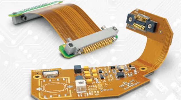
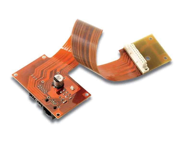
A flexible circuit, also known as a flex circuit or flexible printed circuit board (PCB), is a technology used to assemble electronic circuits by mounting electronic devices on flexible plastic substrates. Flex circuits can be designed with folded portions and three-dimensional configurations, allowing them to fit into tight or dynamic spaces.
Flex circuits provide many advantages over traditional rigid circuit boards:
- Flexible – Can be bent, folded, and twisted to fit mechanical requirements
- Lightweight – Lighter than rigid boards without compromising circuit integrity
- Thin – Circuits can be extremely thin, increasing space savings
- Durable – Withstands vibration and thermal cycling well
- High Density – Small components and fine lines maximize use of space
- Cost Effective – Efficient manufacturing brings costs down
Flex circuits are widely used in consumer electronics, medical devices, industrial equipment, aerospace applications, and more. The flexibility and compact size make them ideal for many applications where rigid boards would be impractical.
Flex Circuit Materials
Flex circuits can be fabricated from a variety of different materials to meet application requirements:
Substrates
The substrate provides the base layer that components and conductors are mounted on. Common substrate materials include:
- Polyimide (Kapton) – Most common, offers good thermal and chemical resistance
- Polyester (PET) – Lower cost but has lower temperature tolerance
- Polyethylene (PE) – Lowest cost but poor thermal resistance
- PEN – An alternative for improved thermal resistance
- PEEK – For high temperature applications like aerospace
Conductors
Conductors are typically made from copper foil laminated onto the substrate. Other options include:
- Gold – For corrosion resistance
- Silver – High conductivity for power transmission
- Carbon ink – Lower cost than metals
Cover layers
Cover layers protect the conductors and add rigidity. Options include acrylic or polyimide adhesives.
Stiffeners
Additional layers may be added for increased rigidity and support:
- Aluminum
- Steel
- FR4
Flex Circuit Fabrication Process
Flex circuit fabrication involves specialized processes and techniques. The general steps include:
- Design – Circuit layout is created through CAD software
- Photolithography – Photoresist patterns are applied to copper clad laminate
- Etching – Exposed copper is etched away, leaving desired conductor pattern
- Component Assembly – Components placed and soldered to pads
- Encapsulation – Protective coatings are applied over conductors
- Testing – Continuity, insulation resistance, and functional testing
Flex circuits offer more complex assembly options compared to rigid boards:
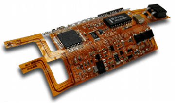
- Multilayer – Flex circuits can be stacked into multilayer configurations
- Rigid-flex – Combines rigid FR4 areas with flexible circuits
- 3D shaping – Flex circuits can be folded and formed into complex 3D structures
- Flexible component assembly – Both surface mount and through-hole components can be used
- Adhesives – Use of anisotropic conductive films and epoxy adhesives
Flex Circuit Applications
The compact size, flexibility, and durability make flex circuits suitable for a wide range of products including:
Consumer Electronics
- Cell phones
- Laptops
- Tablets
- Wearables
- VR headsets
Medical
- Hearing aids
- Pacemakers
- Blood sugar monitors
- Ultrasound probes
Automotive
- Engine control modules
- ABS brake systems
- Transmission sensors
- Backup cameras
Industrial
- Robotics
- Mechanical actuators
- Motor controls
Aerospace
- Avionics systems
- Missile guidance
- UAVs
- Satellites
Flex circuits bring many advantages to these applications:
- Tight space constraints
- Vibration dampening
- Dynamic flexing motions
- Irregular component placement
- Thermal management
Here is an example of a flex circuit application in a consumer electronics device:
| Component | Flex Circuit Features | Benefits |
|---|---|---|
| Cell phone motherboard | <ul><li>Multilayer design</li><li>Rigid and flex sections</li><li>High density traces</li><li>Flexible component assembly</li></ul> | <ul><li>Complex circuitry in compact form factor</li><li>Interconnections between rigid regions</li><li>Maximizes space savings</li><li>Dynamic folding and shaping</li></ul> |
Flex Circuit Design Considerations
Successfully designing and manufacturing flex circuits requires attention to special considerations:
Electrical Design Rules
- Trace widths and clearances must account for flexibility
- Avoid 90 degree bends of traces during flexing
- Account for stresses on solder joints
Mechanical Factors
- Folding radii based on substrate material
- Strain relief for dynamic bending zones
- Adhesive selection at component interfaces
Testing
- Ensure flex durability with dynamic bend cycle testing
- Perform electrical tests in flexed state
Thermal Management
- Heat dissipation is more challenging than rigid boards
- Use thermal adhesives or gap pads when mounting heat sources
By accounting for these factors upfront, flex circuit assemblies can be optimized for reliability and performance.
Flex Circuit Assembly Methods
Specialized assembly techniques are required to produce working flex circuit devices:
Soldering
Reflow soldering is commonly used, but the process must account for:
- Flex board warpage under high temperature
- Adhesive curing profiles
- Component stress during soldering process
Press-fit Components
Can avoid stresses from soldering temperature exposure
Adhesives
- Epoxies bond components and assemble rigid-flex layers
- Anisotropic conductive films provide electrical connections and mechanical support
Crimped Connections
Avoid soldering for mechanical connections
Conformal Coatings
Protect components and exposed traces from environmental damage
Flex Circuit Assembly Equipment
Producing repeatable and reliable flex assemblies requires the proper tools:
- Hand soldering – For prototype and low volume assembly
- Reflow ovens – Automated soldering of surface mount components
- Die bonders – Precise epoxy dispensing and component placement
- Crimping presses – Ensure proper compression of crimped wire terminations
- Conformal coating systems – Controlled application of protective coatings
- AOI systems – Automated optical inspection after assembly
- Flying probe testers – Electrical testing of bare boards
- Fixture based testers – Thorough circuit testing in finished assembly
Investment in this equipment helps ensure flex circuit quality and rapid production scale-up when needed.
Inspection and Testing
Thorough inspection and testing is critical to ensure reliable flex circuit assemblies:
- Visual inspection – all solder joints, epoxy bonds, component placement
- Continuity testing – verify electrical connections meet circuit design
- Insulation resistance – ensure insulation material has not been damaged
- Dielectric withstand voltage – ensure insulation can withstand voltage gradients
- Ground bond testing – verify ground connections properly established
- Functional testing – validate finished circuit operation
Detecting assembly defects early prevents reliability issues in the field.
Flex Circuit Repair Techniques
Despite best assembly practices, some percentage of flex circuit boards will have defects. Where possible, repair of defects is preferred over scrapping the assembly. Common repair techniques include:
- Jumper wires – small gauge wire can bypass damaged traces
- Epoxy glob top – reinforces solder joints and provides insulation
- Trace cuts – isolate damaged portions of circuitry
- Circuit edits – modify circuit to remove damaged component functions
- Trace rebuilding – damaged traces repaired with precision soldering
Successful repairs require skilled operators and repair documentation.
Flex Circuit Design and Assembly Houses
Companies that specialize in flex circuit fabrication and assembly provide valuable expertise and production capacity:
- Design services – assist with CAD layout, DFM analysis, prototyping
- Volume production – scale from prototypes to high volume manufacture
- Supply chain management – procurement of components and materials
- Testing services – continuity, hipot, functional test capabilities
- Repair capabilities – skills and tools for rework and repair
Partnering with a flex assembly expert helps bring flex designs to market faster and more economically.
Conclusion
Flex circuits provide design and assembly options not possible with rigid printed circuit boards. The compact size, dynamic flexing, and rugged reliability make flex circuits an enabling technology across many industries and applications. However, specialized design and manufacturing techniques must be used to fully leverage the benefits of flex circuits. Partnering with an experienced flex circuit assembly house enables rapid development and high volume production of high quality flex assemblies.
Flexible Circuit Assembly FQA
Here are some frequently asked questions about flexible circuit assembly:
What are some key considerations when designing a flex circuit?
Some key design considerations include:
- Minimizing 90 degree trace bends in dynamic flexing areas
- Providing adequate trace widths and spacing for flexibility
- Managing heat dissipation due to limited flex board thickness
- Accounting for stresses on components during flexing
- Providing strain relief in high flexion areas
What types of components can be assembled onto flex circuits?
Flex circuits support assembly of both surface mount and through-hole components. Typical component types include:
- Chip resistors and capacitors
- QFN and BGA packages
- Connectors
- Switches
- LEDs
- Crystals
- Sensors
Both leaded and leadless components can be accommodated.
How are components attached to flex circuits?
Common flex component assembly methods include:
- Reflow soldering of SMT components
- Through-hole soldering
- Conductive epoxy adhesive bonding
- Anisotropic conductive films
- Mechanical pressing of press-fit components
- Crimped wire connections
Flex circuit assemblies may use a combination of these techniques.
How are multilayer flex circuits constructed?
Multilayer flex circuits interconnect rigid boards and flexible layers. Assembly techniques involve:
- Adhesive lamination
- Laser via drilling
- Plated through holes
- Staggered layer design
- Solid metal planes for rigidity
This allows complex flex-rigid designs.
How is flex circuit assembly tested?
Testing of flex assemblies includes:
- Visual inspection of solder joints
- Continuity testing
- Insulation resistance
- Dielectric withstand voltage
- Ground bond testing
- Functional testing
Testing should include dynamic flexing to replicate use conditions.


Leave a Reply