Introduction to Flex PCBs
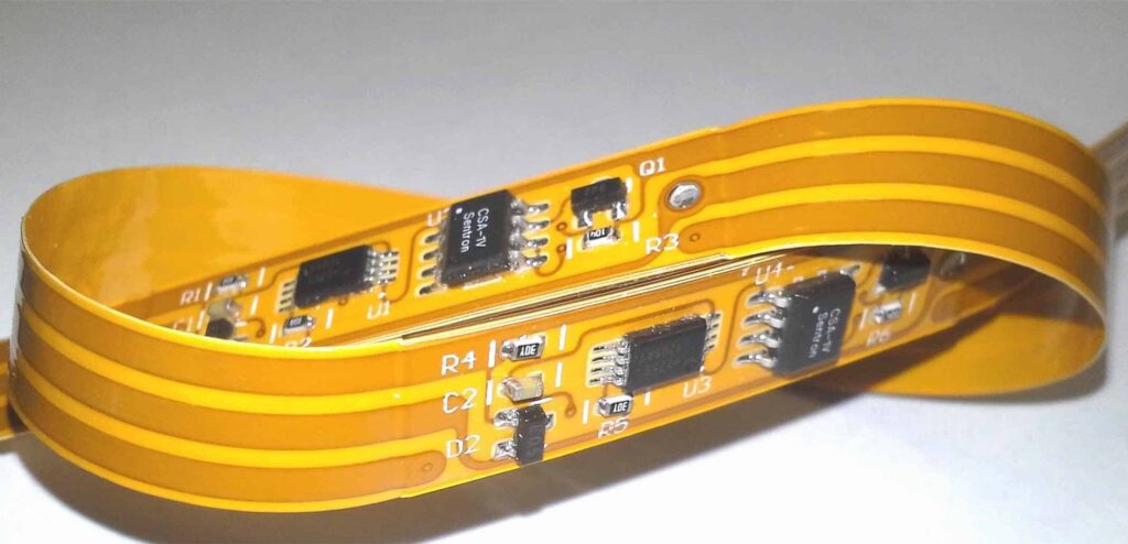
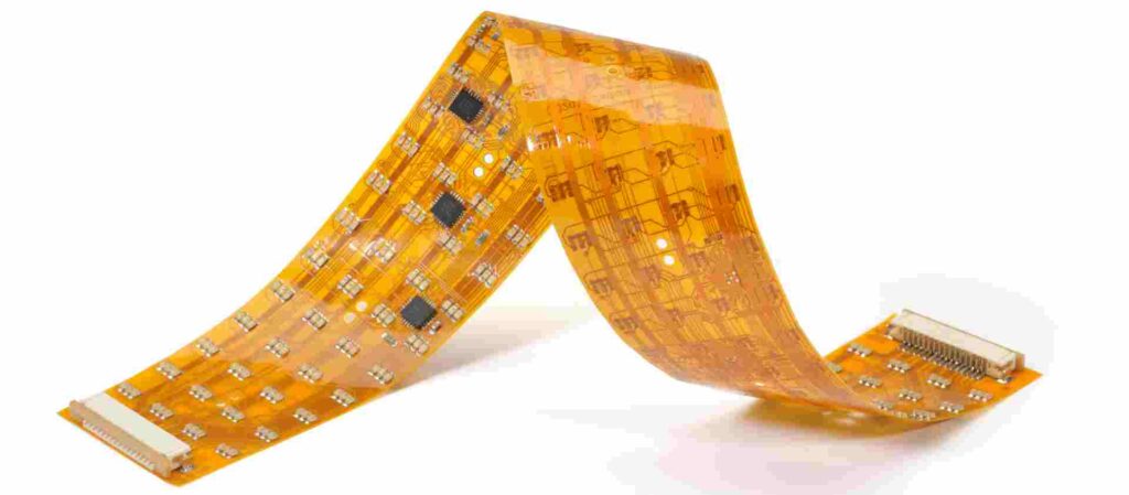
A flexible printed circuit board (flex PCB or flex circuit) is a type of printed circuit board made of flexible materials like polyimide. Unlike traditional rigid PCBs, flex PCBs can bend and flex while still maintaining their electrical connections. They are widely used in products requiring mechanical flexibility such as wearable devices, medical equipment, consumer electronics etc.
The use of flex PCBs provides many advantages:
- More compact and space efficient routing of traces
- Can conform to different product shapes
- Withstand vibration, shock, and repeated motion
- Lower weight compared to rigid boards
However, assembling surface mount components on flex PCBs can be more challenging than rigid boards. This guide covers the entire flex PCB SMT assembly process and key considerations.
Flex PCB SMT Assembly Process

The surface mount assembly process for flex PCBs follows the same main steps as rigid PCB assembly:
Solder Paste Printing
Solder paste is printed on the pads of the flex board to deposit the solder for component attachment. Stencil thickness, aperture size, print pressure are critical factors for high quality printing. Metal stencils are preferred over plastic stencils. Laser cut stencils with electroformed walls provides the best print definition.
Component Placement
Surface mount components are accurately placed on the flex board solder pads. Flexibility of the board makes it more difficult to handle and achieve precise placement. Most SMT assembly equipment have specialized clamping mechanisms to hold the flex boards securely during placement.
Reflow Soldering
The flex board goes through a reflow oven to heat up the solder paste and attach the components. The heating profile is optimized to avoid excessive warping of the thin flexible material.
Conformal Coating
A protective coating is usually applied to prevent corrosion and enhance reliability. Flex boards are more prone to mechanical wear and tear during use. The coating provides insulation, moisture resistance and strengthens solder joints from vibration and shock loads.
Testing and Inspection
Electrical testing validates all connections and verifies proper functioning of the populated board. Automated optical inspection (AOI) checks for defects like missing solder, misaligned components etc. Any rework is done before final inspection approval.
Key Considerations for Flex PCB Assembly
Flex PCBs require careful handling and planning for an efficient SMT production process:
Board Stabilization
The thin flexible material is susceptible to bending and warping in assembly equipment. Proper tooling and fixturing ensures the board is immobilized and stable throughout the process.
Solder Paste Printing
A fine pitch stencil with thinner walls and openings matched to pad size is essential. Low tack solder paste avoids solder balls and bridging. Enclosed print heads provide even print pressure.
Component Placement
Precise component centering is critical and avoids tombstoning. Pick and place systems need special clamping jigs and operation modes optimized for flex board handling. Smaller nozzle tips improve accuracy.
Reflow Profile
A controlled ramp up rate prevents board bowing while heating. The peak temperature is minimized to maintain board stability. Multiple zone convection reflow ovens provide the best results.
Conformal Coating
Select the appropriate coating for flexibility, insulation resistance, moisture protection, and repairability needs. Dispense and cure the coating with methods suitable for flex boards.
Testing and Inspection
Flying probe testing provides non-contact electrical testing well-suited for flexible boards. Optical inspection tools require fixtures to hold down the board.
Tooling and Fixtures
Dedicated tooling for flex boards should be used in each process step. Appropriate clamping jigs, nests, conveyors, and test fixtures ensure smooth handling and accuracy.
Flex PCB Assembly Equipment
Specialized flex PCB assembly equipment improves reliability, precision, and efficiency:
Solder Paste Printing
- Laser cut stencils optimized for flex board printing
- Semi-automatic printers with board holders and enclosed print heads
- Automatic optical print inspection systems
Component Placement
- High precision pick and place machines with flex board modes
- Vacuum systems to immobilize boards
- Automatic optical placement inspection
Reflow Soldering
- Multi-zone convection reflow ovens with custom profiling
- Laser assisted soldering systems
- Thermal profiling tools to optimize oven settings
Conformal Coating
- Precision conformal coating equipment for selective dispensing
- UV cure ovens suitable for heat-sensitive boards
- Automated coating inspection tools
Testing and Inspection
- Flying probe testers
- ICT fixtures to secure flex boards
- Advanced 2D and 3D AOI systems
- Automated x-ray inspection
Handling and Storage
- ESD safe flex board storage racks
- Custom board carriers and handlers
- Flex board specific work instructions
Flex PCB Assembly Challenges

Some key challenges faced during flex PCB assembly include:
- Maintaining precision and accuracy on thin flexible boards
- Preventing warpage of boards during soldering
- Achieving complete component wetting on flex materials
- Controlling registration of multilayer flex boards
- Managing the additional handling requirements
- Repairing and reworking components on flex boards
- Finding flex board specific defects during inspection
- Implementing effective process controls
Using the right set of equipment, materials and process best practices can help overcome these challenges.
Flex PCB Assembly Quality Management
Robust quality control is essential due to the tighter tolerances of flex PCB assembly. Key elements include:
- Statistical process control tracking of defects
- Clear inspection criteria for each process step
- Operator training on flex board handling
- Measurement systems analysis for inspection tools
- Data collection and analysis of process performance
- Corrective actions based on root cause analysis
- Continuous improvement through lean tools
With disciplined quality management, the reliability and yields for flex PCB assembly can match those of rigid boards.
Applications of Flex PCB Assemblies
Here are some examples of products using populated flex boards:
Consumer Electronics
- Mobile phones
- Laptop and tablet computers
- Smartwatches and fitness bands
- Digital cameras
- Charging cables
Medical Equipment
- Hearing aids
- Portable patient monitors
- Surgical devices and implants
- Dental cameras
- Glucose monitors
Automotive Use
- Engine control units
- EV and hybrid electronics
- Seat control panels
- Infotainment dashboards
- Brake light circuits
Industrial Applications
- Robotics and motion control systems
- Touch screen HMIs
- IoT and sensor devices
- LED lighting
- Avionics systems
Flex-Rigid Boards
Combining rigid and flex materials on the same board expands PCB design possibilities. Flex-rigid PCBs integrate small rigid regions for components with flexible connections. The assembly process requires expertise in handling these hybrid boards.
PCB Assembly for Prototype and Low Volume Production
For prototyping or ramping up a new product, assembling a small number of flex boards is preferred. This allows validation of the design before high volume production.
Specialized PCB assembly providers offer low to medium volume flex board assembly with quick turnaround times. They have the right equipment and expertise to handle small batches and provide exceptional quality.
Using an expert flex board assembly service streamlines product development cycles and provides a seamless transition to mass production.
Conclusion
Assembling surface mount components on flexible PCBs demand careful process and material selection. With the right set of assembly equipment optimized for flex boards, skilled operators, and robust quality systems, flex PCBs can be reliably manufactured with high yields. For low to medium volume production, specialized assembly providers offer rapid prototyping and pre-production services to accelerate product development schedules.
Flex PCB SMT Assembly FAQs
Here are some frequently asked questions about flex PCB assembly:
Q: What are some key benefits of using flex PCBs?
A: Flex PCBs provide design flexibility, space savings, vibration resistance, lighter weight, and reliability in demanding applications. Products can be designed with shapes and bends not possible with rigid boards.
Q: How are flex PCBs fabricated and can components be embedded?
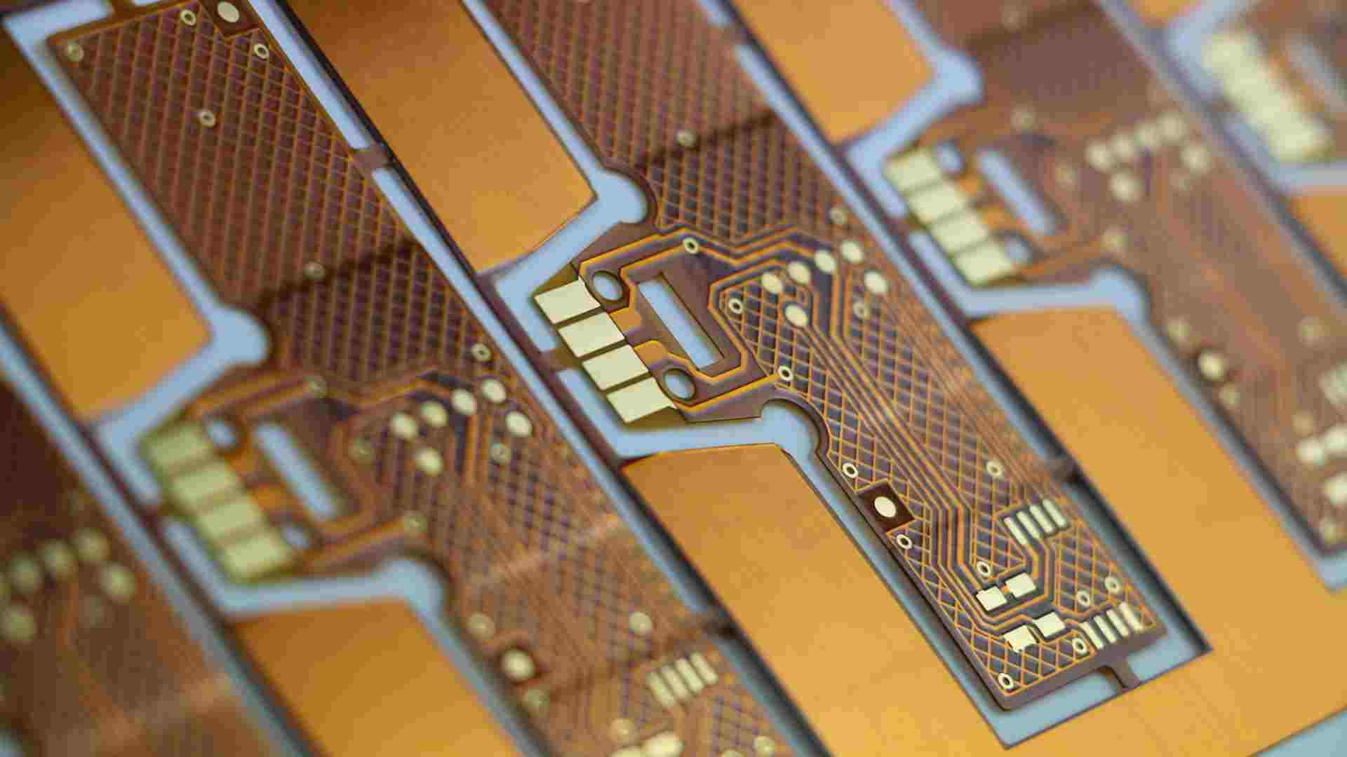
A: Flex boards are fabricated by patterning rolls of flexible dielectric material like polyimide with etched copper traces. Additional layers are laminated using adhesive sheets. Passive components can also be embedded into the layers.
Q: What are some challenges with handling thin flex PCBs?
A: Flex boards are fragile and require careful handling at each step – stencil printing, pick and place, reflow soldering, testing. Dedicated jigs and fixtures are needed to avoid bending or warping.
Q: How is rework done on flex PCB assemblies?
A: Rework can be done using hot air tools, mini soldering irons, and manual vacuum pick tools suitable for flex boards. Preheating helps avoid damage during component removal and replacement.
Q: Can rigid components be mounted on flex PCB assemblies?
A: Yes, but the junctions between rigid components and flex sections require some clearance. Strain relief patterns help manage stresses from motion. Rigid-flex boards combine both types of sections.


Leave a Reply