A flex harness, also known as a flex circuit or flexible printed circuit board (PCB), is a type of circuitry made from flexible materials like polyimide film. Unlike traditional rigid PCBs, flex harnesses can bend and flex to accommodate connections between components in tight or moving spaces. They provide reliable interconnections while minimizing space requirements.
Flex harnesses are widely used in today’s electronics for everything from consumer devices to industrial and medical applications. As products continue getting smaller and more powerful, flexible PCBs help pack more functionality into less space.
This article provides an overview of flex harness PCB design, manufacturing processes, pros and cons, and trends shaping the market.
Flexible Circuit Design Considerations
Designing a successful flex harness requires accounting for the intricacies of flex PCBs. Here are some key design considerations:
Materials
The most common materials used are polyimide films like Kapton or Upilex. These provide flexibility and durability over thousands or millions of flex cycles. Other options include polyester films and PEN films. Choosing the right materials for an application requires evaluating factors like flex life, temperature resistance, chemical resistance, flame retardance, and more.
Layer Stackup
Typical flex constructions involve adhesive layers bonding copper traces between two polyimide film layers. More complex rigid-flex designs might incorporate multiple laminated layers with flexible and rigid sections. The layer stackup must balance flexibility with thickness and insulation needs.
Conductor Spacing and Width
Narrower trace widths allow tighter spacing and routing of connections. Typical widths range from 0.10mm to 0.30mm. Recommended spacing is at least 3X the conductor thickness. Wider traces may be needed for high current capacity.
Bend Radius
Sharper flexing puts more strain on the materials. The minimum bend radius is determined by factors like conductor thickness, spacing, layer count, and flex life requirements. Typical minimum inside bend radii range from 2X to 10X the total thickness.
Stiffeners and Strain Relief
Stiffeners made from materials like acrylic or polyimide may be added to provide support at connection points or avoid localized over-flexing. Strain relief features can also be designed into the flexible area.
Terminations
Connections from the flex PCB to electronics or cables require robust, reliable terminations. Common options include soldered pads, sockets, connectors, crimped pins, and more.
Shielding
In some applications, shielding against EMI or environmental elements is needed. This can be achieved by adding conductive layers or coatings in the flex circuit laminate.
Testing
Prototypes should be put through testing to verify the design performs as expected when flexed repeatedly. Issues like conductor cracking and delamination can be identified and corrected.
Flex Harness Manufacturing Processes
Producing a reliable flex harness at scale requires specialized manufacturing techniques. Here is an overview of key processes:
Imaging
The desired conductor pattern is transferred to a photoresist layer on the laminate using lithographic printing. Photoresist chemistries specially formulated for flex circuitry are used.
Etching
The unexposed photoresist is developed away, leaving the desired conductor pattern behind. The copper is then etched away from unprotected areas, isolating the conductors.
Laminating
Adhesive films are added to bond the etched copper traces between insulating polymer layers. Heat and pressure are applied to cure the adhesive. Rigid sections may be part of the laminate.
Die Cutting
Once cured, the overall flex harness shape is cut out using processes like rotary or steel-rule die cutting. Connection tabs, cutouts, and other features are also cut.
Plating
Exposed copper traces may be plated with immersion tin, silver, nickel/gold and other finishes for protection against oxidation and improved connections.
Solder Mask
A solder mask layer is added for insulation. Openings are created over pads and solders using photoimaging or screen printing processes.
Testing
100% electrical testing validates the circuits meet specifications. Automated optical inspection looks for potential defects. Samples also undergo environmental stress testing.
Assembly
Secondary operations like adding connectors, stiffeners, or shielding materials are done to complete the harness for integration into products.
Benefits and Applications of Flex Harnesses
Some key benefits of using flex harnesses include:
- Compact connections – Bends and folds to fit in tight spaces where rigid PCBs won’t work.
- Dynamic flexing – Withstands repeated bending and flexing motion. Enables interconnections between moving parts.
- Lightweight – Weighs less than alternatives, important in mobile devices.
- Reliability – Proven technology that avoids wires & cables. Provides high connection reliability.
- Production scalability – Mature industry with ability to produce large volumes.
These advantages make flex PCBs well-suited for:
- Consumer electronics – Cell phones, laptops, cameras, gaming devices.
- Automotive – Engine systems, brake and accelerator connections, mirrors.
- Aerospace and defense – Guidance systems, engine controls, radar.
- Medical – Hearing aids, patient monitoring, implants.
- Industrial – Robotics, machinery, kiosks, inspection equipment.
As electronics evolve, flex harnesses enable lighter, more dynamic, and more compact product designs across industries.
Consumer Electronics Applications
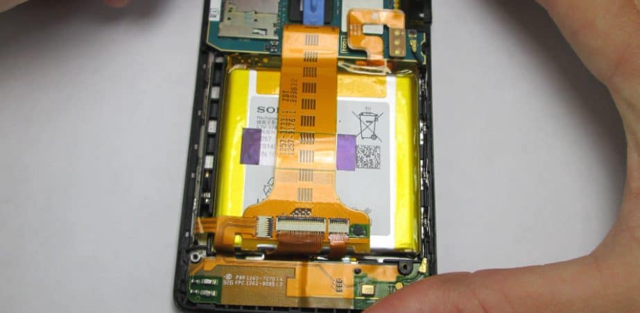
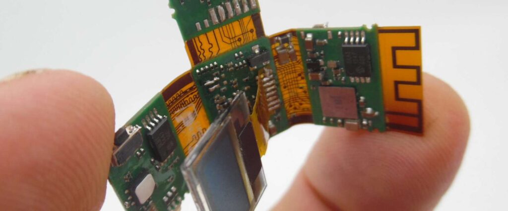
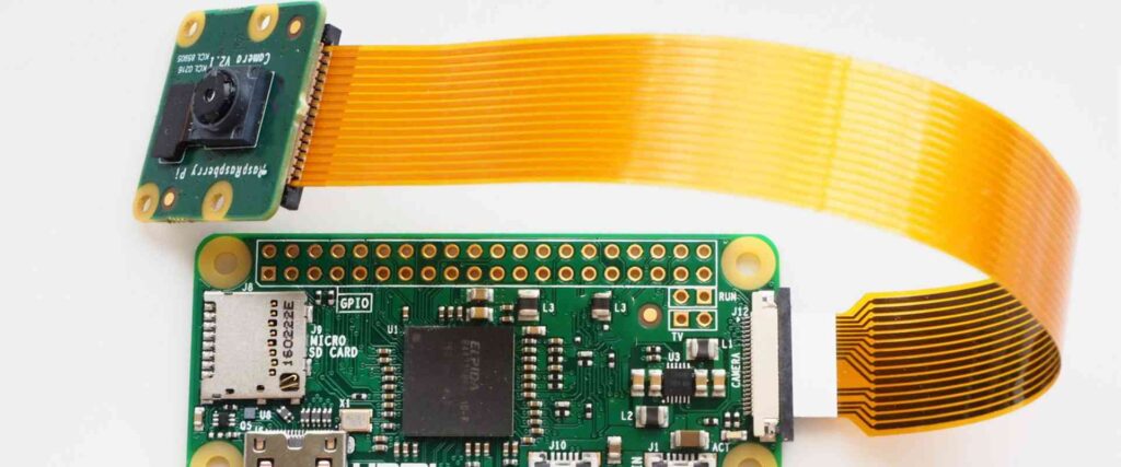
Flex circuits are ubiquitous in today’s consumer electronics. Mobile phones use flex PCBs for connections between the mainboard and display, battery, cameras, buttons, fingerprint sensors, and more. Laptops incorporate flex harnesses for screen and keyboard connectivity as well as internal wiring. Countless other consumer products from wearables to appliances to gaming systems leverage compact flex circuits.
Some common ways flex harnesses are designed into consumer electronics include:
- Displays – video, touchscreen, OLED flex attachments
- Component interconnects – processors, memory, sensors, batteries
- Board-to-board connections – replacing connectors and cables
- PCB stiffeners – support for rigid-flex areas
- Hinge & coiled flex cables – adjustable connections
- Ribbon cables – parallel wiring between PCBs
As electronics get more compact and lightweight, flex circuits will continue growing as the ideal solution for interconnections.
Automotive Applications
Vehicles make extensive use of flex harnesses due to the dynamic environment and space constraints. Flex circuits provide reliable performance despite vibration, shocks, and extreme temperatures. Typical automotive applications include:
- Powertrain – Engine, transmission, exhaust, fuel systems
- Body controls – Door wiring, seat adjustments, mirrors, wipers
- Interior electronics – Displays, buttons, sensors, lighting
- ADAS systems – Cameras, radar, lane detection, collision avoidance
- Battery systems – High voltage wiring and monitoring
The move towards electrification, autonomous driving, vehicle digitization, and advanced safety features will drive increased adoption of flex harnesses for in-vehicle data and power transmission.
Medical Applications
Medical devices often require compact, lightweight interconnections. Some examples of how flex circuits are used:
- Hearing aids – Inter-component wiring in miniature packages
- Patient monitors – Dynamic cabling for ECG, pulse oximetry, blood pressure
- Endoscopes – Imaging sensor integration and steering
- Implants – Connections from pacemakers, neurostimulators to leads
- Robotics – Wiring for surgical tools and manipulators
- Diagnostic systems – Flex interconnects for carts, imaging, labs
Flex harnesses allow medical devices to become smaller and more portable while maintaining patient safety and care quality.
Flex Circuit Design and Manufacturing Trends
As flexible circuits become more advanced, designers continue pushing the boundaries of the technology. Some leading trends shaping flex harnesses today include:
- Higher densities – Construction innovations allow smaller widths and spaces down to 50 microns.
- 5G applications – High frequencies demand tightly controlled impedances.
- Improved flex life – New materials flex over 50 million cycles.
- Finer lines and spaces – Line widths down to 15 microns are in development.
- Advanced semiconductor packaging – Direct chip attach with fan-out flex harnesses.
- Higher data rates – Modern protocols like USB4 need matched impedances up to 16+ GHz.
- Lower loss materials – PEN films for reduced signal loss at high frequencies.
- Flex-rigid-flex – Captures advantages of both rigid and flexible PCBs.
- Bend radius reduction – Allows tighter folding via new conductor/dielectric development.
- Additive processes – Reduce waste versus subtractive etching.
These innovations will enable flex circuits to meet the needs of emerging applications from autonomous vehicles to flexible displays to implantable medical devices and more.
Pros and Cons of Flexible Printed Circuits
While flex PCBs provide invaluable connectivity solutions, they also have some downsides to consider. Here is a summary of key pros and cons:
Pros
- Compact, lightweight, and thinner than wires
- Dynamic and repeated flexing/bending
- Vibration and impact resistance
- Excellent electrical performance at high frequencies
- Mature manufacturing with high volume capability
- Generally lower assembly costs
- Reliable connectivity and long flex life
Cons
- Generally higher production costs than rigid PCBs
- Limited in number of layers that can be laminated
- Requires specialized design expertise
- Lower current carrying capacity than wires
- Repairs can be difficult or impossible
- Longer assembly time due to manual operations
- Progressive conductor failure over longtime flexing
By understanding these tradeoffs, engineers can effectively leverage flexible circuits while mitigating limitations through careful design and process choices.
Flex Circuit FQA (Frequently Questioned Answers)
Here are answers to some often asked questions about flex harnesses:
What are some alternatives to flex circuits?
Common alternatives include wire cabling, rigid PCBs, connectors, and custom flex cables. Each has pros and cons to consider. Rigid-flex PCBs combine rigid and flex sections as needed.
How long is the typical design life of a flex circuit?
Properly designed flex harnesses can reliably flex many millions of times without failure. Materials, trace width, and bend radius determine life expectancy. Careful testing validates lifespan.
What types of connections work with flex PCBs?
Common methods include soldering, press-fit pins, sockets, crimped connections, and various connectors. Anisotropic conductive films or adhesives are also popular for attachments.
Can flex circuits be repaired?
Unfortunately flex PCB repairs are very difficult and usually not practical or economical. It’s generally advisable to design sufficient reliability into the product upfront to avoid needing repairs.
How small can flex circuit conductors be?
Modern flex PCBs achieve trace widths down to around 15 microns, though 25-50 microns is more common. Widths down to 10 microns are in development. Narrower widths allow higher connection densities.
How are flex circuits tested?
In addition to standard electrical testing, flex harnesses undergo physical stress testing like bend cycle, torsion, vibration, shock, and environmental testing to validate robustness. Samples are often cross-sectioned and inspected under microscope for signs of damage.
In summary, flex harnesses provide compact, reliable connectivity in products where dynamics, space constraints, or repeated motion demands flexible interconnections instead of rigid PCBs or wiring. Advancements in materials, design, and manufacturing continue to expand flex circuit capabilities and drive increased adoption across industries.


Leave a Reply