Introduction
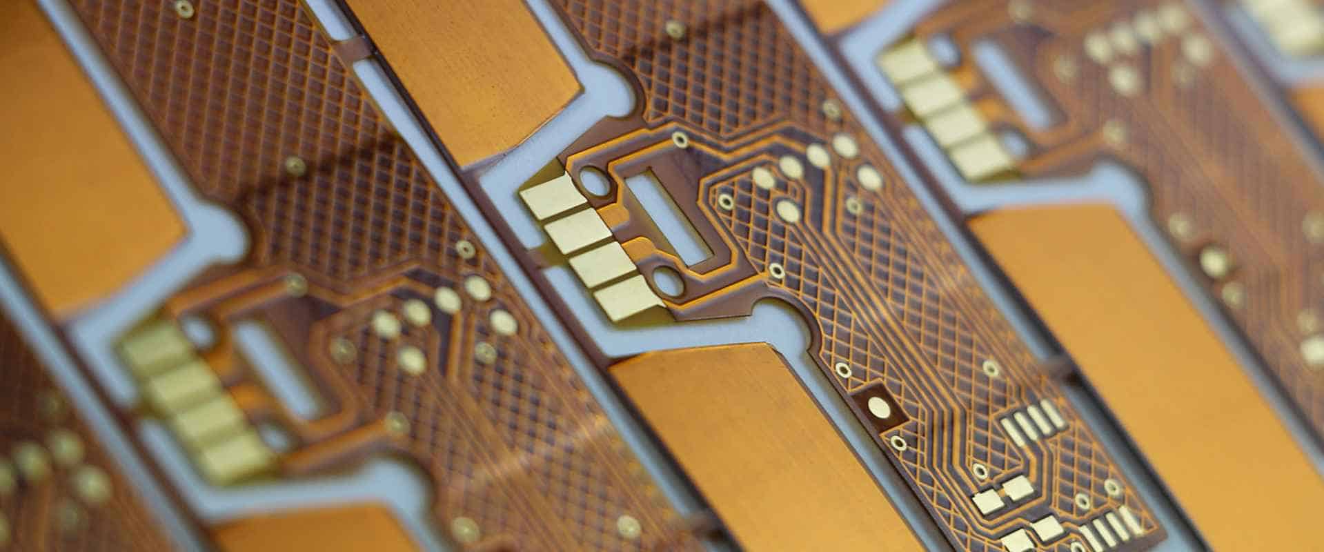
A flex circuit, also known as a flexible printed circuit board (PCB), is a type of circuitry that is designed to bend and flex. Flex circuits allow electronic connections in applications where rigid printed circuit boards would be impractical. They are used in a wide range of products including medical devices, consumer electronics, automotive components, aerospace systems, and industrial equipment. As flex circuits grow in popularity, the market for flex circuit manufacturers is also expanding. Choosing the right partner is critical to ensure your flex circuit project is produced properly. This guide provides an overview of things to consider when selecting a flex circuit manufacturer.
Flex Circuit Applications and Benefits

Flex circuits provide many advantages over traditional rigid circuit boards:
- Adaptability: Flex circuits can bend and twist to fit unique shapes and spaces in products. This allows circuitry to work in tight, complex designs.
- Durability: The flexible material makes circuits more shock and vibration resistant. Flex circuits also tolerate repeated bending better than rigid boards.
- Weight savings: Removing rigid substrates reduces the weight of finished products. This is advantageous in aerospace, automotive and portable electronics.
- Reliability: Flex circuits have fewer solder joints and connections than rigid-flex designs. This results in increased reliability and reduced failure points.
- Miniaturization: Smaller and thinner form factors are possible with flexible circuits. They enable innovators to reduce the footprint of electronic devices.
Flex circuits are used across many industries:
- Medical: Hearing aids, blood glucose monitors, ultrasound wands, wearable monitors, and other healthcare products use flex circuits extensively.
- Consumer Electronics: Cell phones, laptops, tablets, cameras, and home appliances incorporate flexible circuits.
- Automotive: Flex circuits handle engine controls, lighting, safety systems, sensors, and in-vehicle electronics.
- Military/Aerospace: Missiles, satellites, guidance systems, and other defense and space applications rely on flex circuitry.
- Industrial: Flexible circuit boards support robotics, instrumentation, automation, IoT, and other industrial technologies.
This diversity of applications highlights the versatility and utility of flex circuit technology. As products continue getting smaller and more advanced, flex circuits will play an integral role.
Flex Circuit Materials and Construction
Although designs vary based on the application, flex circuits have some common characteristics:
Substrate
The flexible substrate is the base material or foundation of the circuit. The most common options include:
- Polyimide (Kapton)
- Polyester (PET)
- Polyethylene (PE)
- PEEK
Conductors
Etched copper foil is typically used to create the conductive pathways or traces. Other options include aluminum, gold, nickel, and silver.
Cover layer
A coverlay or other coating is often applied over the conductor layer. This protects the copper traces from damage. Common cover lay materials are acrylic, polyimide, solder mask, and Nitrile.
Adhesive
Adhesive bonds the different layers together. Common options are acrylic, epoxy, or heat activated adhesive.
In addition to these basic components, some flex circuits incorporate stiffeners, shields, solder pads, test points, and other features. The cross-section below shows a typical single-sided flex circuit construction:
The layout and materials selected will depend on the operating environment and other requirements of your specific application.
Flex Circuit Design Considerations
Designing a flex circuit requires close collaboration between you and potential manufacturers. Here are some key considerations:
- Circuit layout: The arrangement of traces and components impacts flexibility. Long continuous traces that follow the flex direction work best.
- Minimum bend radius: This spec defines the smallest radius a flex circuit can be bent without damage. It’s driven by material selection.
- Layer stackup: Simple 1-2 layer circuits offer more flexibility; multilayer designs provide more complexity.
- Component placement: Smaller, flat components work best. Avoid large, bulky parts in the flexing areas.
- Plated through holes (PTHs): Limit the number of holes drilled through all layers to maximize flex life.
- Stiffener integration: Adding stiffeners prevents folds and provides mounting stability, but reduces bendability.
- ESD/EMI control: Shielding, insulation, or specialized materials may be needed for electrical requirements.
- Termination style: Exposed pads vs. connectors vs. solder joints impact cost and ease of assembly.
Your flex circuit partner will help fine-tune the design based on manufacturability and reliability testing specific to your application.
Key Flex Circuit Manufacturing Capabilities
Design is only the first step. The selected manufacturer must also have proven expertise in specialized flex circuit fabrication techniques:
Photolithography
High-resolution imaging is used to transfer the conductor pattern from CAD onto the flex board substrate.
Etching
Wet chemical or plasma processes remove unwanted copper from the substrate to create isolated traces.
Bonding
Adhesives laminate together the flex layers into a complete circuit. Precise control prevents warping.
Cover coat
The protective top layer is screen printed or laminated onto the conductor side of the board.
Via formation
Ability to laser drill or mechanically punch vias through the flex circuit layers.
Metalization
Deposits conductive material on the interior surface of drilled vias.
Assembly
Some vendors provide component attachment, soldering, testing, and other assembly services.
Ideally the manufacturer handles as many of these processes in-house as possible to reduce supply chain variability. Ask about their specific capabilities before selecting a partner for your project.
Provider Evaluation Criteria
Once you understand the desired flex circuit design and manufacturing features, use the following criteria during your selection process:
| Evaluation Criteria | Description |
|---|---|
| Industry experience | Number of years manufacturing flex circuits; examples of previous work. |
| Quality certifications | ISO registrations demonstrate commitment to consistency and process control. |
| Design support | Ability to provide recommendations during design to optimize manufacturing. |
| Flex materials | Variety of flexible substrate, conductor, and cover layer options. |
| Fabrication capabilities | In-house vs. outsourced production processes. |
| Secondary operations | Assembly, bonding, testing, and other value-added services. |
| Reliability testing | Capabilities for flex life, environmental stress, vibration exposure, etc. |
| Prototyping services | Options for small test runs and quick turnaround samples. |
| Facilities and equipment | Investments in new technologies and production equipment. |
| Capacity and scalability | Ability to meet demands of high or low volume orders. |
Collecting detailed responses in each category makes it easier to compare strengths of potential suppliers. Be sure to request process qualification data and other technical documentation as well. The goal is to select a flex circuit company that can consistently meet your cost, quality, and delivery requirements.
Leading Flexible Circuit Board Manufacturers
Many providers specialize in flex PCB fabrication. Here are a few of the top manufacturers serving customers globally:
Flexible Circuit Technologies (FCT)
FCT offers design, prototyping and manufacturing of complex flex circuits. Their capabilities include multilayer flex, rigid-flex, HDI, and backplane designs.
All Flex
This Minnesota-based provider fabricates a wide range of single, double, and multilayer flex circuits. They have particular expertise in medical devices.
Dycotec Materials
UK company providing specialized services in the development and production of thin flexible circuits and sensors.
Flex
Large flex circuit supplier supporting defense, medical, industrial, and other markets from their global facilities.
MFLEX
MFLEX specializes in flex and rigid-flex PCBs for aerospace, military, telecom, and other quality-driven industries.
Compunetics
Compunetics offers design, prototyping, and volume production of flex, rigid-flex, and rigid PCBs at their TH, USA facility.
These manufacturers represent a sampling of reputable flex circuit companies around the world. With their expertise and production capabilities, they can deliver flex PCB solutions tailored to your specific application requirements.
Getting Started with Your Flex Circuit Project
Breaking into the world of flex PCBs may seem daunting if you have experience with only traditional rigid boards. However, the potential benefits make it worthwhile to learn the nuances of flex circuit design and fabrication. Follow these steps to begin:
- Clarify objectives – Define the capabilities you want a flex circuit to provide. How will it improve upon a rigid board?
- Engage a designer – Even if you have internal PCB layout skills, work with a flex circuit specialist at first. They can ensure your design accounts for specialized construction and assembly requirements.
- Select materials – Use the target application parameters to narrow down appropriate flexible substrate, conductor, and cover layer options.
- Build prototypes – Test out multiple versions with a flex circuit manufacturer experienced in prototypes. Optimize the design based on their feedback.
- Identify production partners – Thoroughly evaluate manufacturers against your cost, quality and delivery needs. Request their process qualifications.
- Refine and release – Finalize board layout for production after adequate testing. Define quality, inspection, and acceptance protocols.
With smart planning upfront, your organization can gain all the benefits flex circuits offer. The right partner helps avoid missteps and ensures you receive well-constructed boards. Use the guidelines in this article to make informed flex circuit decisions.
Frequently Asked Questions
Q: Are flex circuits expensive to produce?
A: Flex circuits used to be quite costly, but improved manufacturing techniques have reduced prices significantly. They remain more expensive than rigid PCBs, but the benefits often justify the premium for many applications. Focus on functionality first, then optimize cost where possible.
Q: Can components be soldered onto flex circuits?
A: Yes, components can be surface mounted or soldered using conventional techniques. Avoid placing large, heavy parts in areas of maximum flex or bend. Use adhesives when needed for added stability.
Q: What limits the minimum bend radius?
A: The substrate material used is the primary factor determining bend radius. Polyimide allows the tightest folds down to 0.10mm radius. Other common materials range from 2-10mm minimums.
Q: Is it possible to create multilayer flex circuits?
A: Yes, flex circuits can have multiple conductive layers stacked and interconnected to create complex circuitry. This provides design flexibility at the expense of some bendability.
Q: How long do flex circuits last in operation?
A: Properly designed and manufactured flex circuits can endure millions of dynamic flex cycles. Visual inspection and electrical testing can identify wear over time. Lifespan varies based on materials, usage, and environment.


Leave a Reply