Introduction
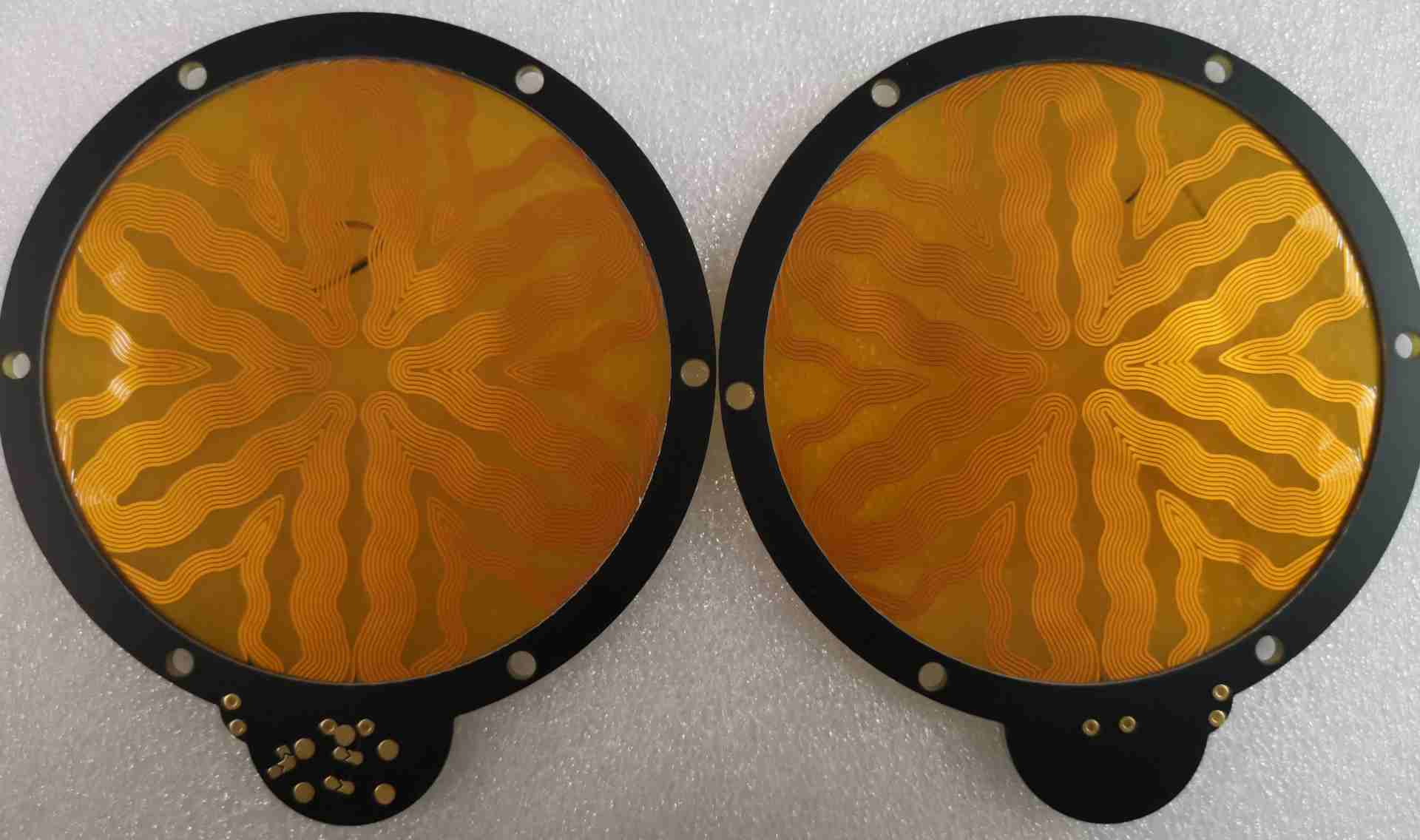
Flex circuits, short for flexible printed circuits, represent an innovative advancement in electronics design and manufacturing. As the name implies, flex circuits comprise thin, bendable circuit boards constructed using flexible polymer substrates and conductive materials. This flexibility allows flex circuits to be bent, folded and formed into a wide range of shapes and configurations. The technology is enabling lighter, thinner and more reliable electronic devices across nearly every industry.
Compared to traditional rigid printed circuit boards (PCBs), flex circuits provide many advantages:
- Extremely lightweight and thin profile
- Can conform to movable and tight spaces
- Withstand repeated bending without damage
- Simplified assembly and installation
- Improved reliability and product life
- Lower assembly costs and weight versus discrete wires
This article provides an in-depth overview of flex circuit technology, manufacturing processes, design considerations and applications driving its rapid growth.
Construction of Flex Circuits
Flex circuits consist of three key elements bonded together:
Flexible Substrate
Polymer films like polyimide or polyester typically 12 to 100 micrometers thick provide the flex circuit base. The most common is polyimide which offers high heat and chemical resistance.
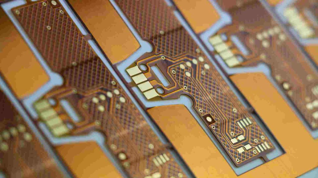
Conductive Traces
Usually copper foil laminated or plated onto the substrate forms the conducting paths of the circuit. Other trace materials include gold, silver or tin alloys.
Coverlay/Bonding Material
A thin insulating coverlay protects the traces from damage or shorting. Common materials are solder mask, acrylic or polyimide.
By selecting appropriate thicknesses and properties of these materials, flex circuits can be engineered to meet electrical, mechanical and thermal requirements.
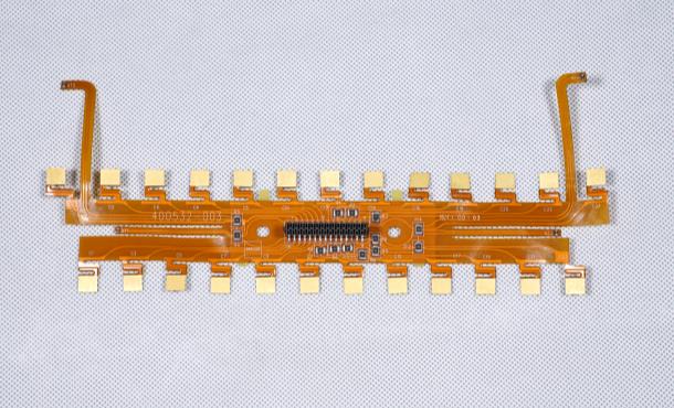
Configurations
Basic flex circuit constructions include:
- Single-sided – Conductors on one side only
- Double-sided – Conductors on both sides
- Multilayer – Alternating stacked layers of substrate and traces
- Rigid-flex – Combines flex circuit sections with rigid PCB sections
Flex Circuit Design Considerations
Successfully designing flex circuits requires considering factors like:
- Bend radius – Avoid sharp bends. Inside edges experience highest strain.
- Flexion areas – Reinforce areas of repeated bending.
- Conductor layout – Optimize placement to minimize length. Account for movement and deformation.
- Board stiffness – More copper layers increase stiffness. Balance flexibility with sturdiness.
- ESD protection – Flex boards are prone to electrostatic discharge damage.
- Thermal management – Flex circuits conduct heat poorly compared to rigid PCBs.
Following established design rules and standards helps avoid problems and ensures the circuit can be manufactured.
Flex Circuit Fabrication Process
Fabricating flex circuits requires specialized techniques compared to rigid PCBs:
Step 1: Design
Circuit requirements are defined and the board is laid out following flex design rules. CAD tools generate manufacturing files.
Step 2: Material Selection
Substrate, coverlay, adhesive and conductor materials are chosen to meet requirements.
Step 3: Imaging
Photolithography transfers the cuductor pattern onto the substrate using a photomask.
Step 4: Etching
Exposed copper is etched away chemically, leaving only the desired conductor pattern.
Step 5: Coverlay Application
Protective overlay films are bonded to the substrate through heat and adhesive.
Step 6: Via Formation
Holes are drilled through the layers for electrical connections. These are plated with copper.
Step 7: Plating and Coating
Exposed traces are plated to protect against oxidation and improve solderability.
Step 8: Sizing and Testing
Individual circuits are routed from panels. Quality testing checks for defects.
The completed flex assemblies are then sent for component assembly before final product integration.
Applications and Benefits of Flex Circuits
The unique properties of flex circuits make them ideal across industries:
Aerospace
- Mission-critical interconnects for guidance, radar and avionics systems
- Withstand vibration, shock, temperature extremes
- Lightweight compared to cabling
Automotive
- Dashboard electronics, lighting, engine controls
- Flat under-seat mounting versus bulky wiring harnesses
- Can survive vibration and flexing
Consumer Electronics
- Enable lighter, thinner, smaller devices
- Flexible mounting options not possible with rigid PCBs
- Used in smartphones, wearables, IoT devices
Medical
- Implantable devices, disposable health sensors
- Biocompatible and suitable for body contact
- Can accommodate flexible surfaces
Industrial
- Easy installation into tight spaces
- Withstand harsh industrial environments
- Flex-to-cable interconnects for robotics
Military/Defense
- Rugged, reliable circuits for extreme environments
- Used in guidance systems, communications, imaging
Flex circuits will continue gaining applications across industries as the demand grows for smaller, lighter and more dynamic electronic devices and systems.
Key Takeaways
- Flex circuits use flexible polymer substrates to enable thin, bendable printed circuits.
- They withstand repeated flexion and vibration without damage.
- Flex PCB construction involves flexible substrates, thin copper traces and insulating overlay materials.
- Design considers factors like bend radius, thermal dissipation and mechanical robustness.
- Flex manufacturing utilizes specialized techniques compared to rigid PCB fabrication.
- Flex circuits are widely used in aerospace, consumer, medical, auto, and defense applications.
Frequently Asked Questions
What are the main benefits of flex circuits over rigid boards?
The advantages of flex circuits include flexibility allowing compact installation spaces, resistance to cracking under repeated bending, lightweight and thin profile, simplified cabling and assembly, improved reliability and ruggedness in vibration/shock environments.
What types of products use flex circuits?
Applications include consumer devices like smartphones and wearables, automotive electronics, avionics systems, patient monitoring and medical sensors, industrial robotics and automation, and military systems needing reliable interconnects in demanding environments.
What determines the flexibility of a flex circuit?
Flexibility is primarily determined by the thickness and modulus of elasticity of the base substrate material. Polyimide films as thin as 12 microns are very flexible while thicker substrates with more copper layers are stiffer. Design, including bend radii, also impacts flexibility.
How are flex circuits manufactured?
Specialized techniques are required compared to rigid PCB fabrication. Flex manufacturing involves imaging conductors onto flexible polymer substrates using photolithography, etching, bonding overlay films, drilling vias, and testing.
What types of materials are used to make flex circuits?
The core materials are flexible polymer substrates like polyimide or polyester, thin copper foils for conductor traces, and polymer overlay films for insulation. Dielectric materials include acrylic and epoxy adhesives.
In summary, flex circuits enable lighter, thinner, and more reliable electronic devices. As technology improves, they will find increasing applications across industries demanding compact and dynamic circuitry.


Leave a Reply