Introduction
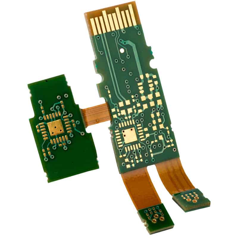
A flex rigid PCB, also known as a rigid flex PCB, combines rigid and flexible PCB substrates into one circuit board. This allows the board to maintain rigidity while also bending and flexing in certain areas. Flex rigid PCBs provide several advantages such as improved reliability, space and weight savings, and design flexibility. However, there are also some potential disadvantages to consider when using a flex rigid PCB. This article will examine the key disadvantages of flex rigid PCBs.
Manufacturing Complexity
One of the main downsides of a flex rigid PCB is that it is more complex to manufacture compared to a standard rigid PCB. The flexible and rigid sections require different processes, materials, and handling. The manufacturability of the design is more difficult with the combination of rigid and flex.
Some specific manufacturing challenges include:
- Layer alignment between rigid and flex areas
- Maintaining registration during lamination
- Separation of circuits between sections
- Integrating stiffeners and covers
- Bonding layers with adhesives
- Folding or bending flex areas
The additional process steps can increase the lead time as well as the cost of the flex rigid PCB. Manufacturers need more specialized equipment and expertise to produce these hybrid boards.
Fabrication Process Differences
The rigid sections of the PCB are fabricated similarly to a normal FR-4 board. However, the flex sections require polyimide flexible dielectric materials. The materials and stackup are optimized for flexibility. The traces in the bend areas are also treated to withstand repeated flexing without cracking.
The core bonding layers help integrate the separate rigid and flex materials into one cohesive circuit board. This is a manual process that requires precision and quality control. Any misalignment or air bubbles can cause failures or reliability issues.
Design Challenges
Designing a flex rigid PCB requires paying careful attention to the layout in both the rigid and flex areas as well as the transitions between them. This more complex design can lead to several potential issues.
Rigid-Flex Transition
The areas where the rigid and flex layers interconnect, sometimes called rigid-flex transition zones, are prone to cracking or separation over time. The coefficient of thermal expansion and mechanical properties differ between the sections. The stresses must be managed through careful junction placement and transition design.
Bend Radius Limitations
The flexible sections have a minimum bend radius requirement based on the materials used. Tight folds can damage the traces and insulation material. The radius limitations may impact the industrial design and use of the product.
Layer Count Restrictions
High layer count boards above 8 or 10 layers are difficult to produce for flex rigid PCBs. The layer count may need to be restricted in complex designs to ensure manufacturability and reliability.
Stackup Development
Developing the optimal stackup requires balancing flex and rigid needs. Thinner dielectrics may be needed in the flex area while thicker layers are preferred in the rigid sections. Stackup tradeoffs impact weight, thickness, and performance.
Thermal Management
The thermal properties differ between rigid and flex areas, which makes cooling more difficult. The combination of materials with different coefficients of thermal expansion also impacts thermal stresses.
Reliability Concerns
Although flex rigid PCBs improve reliability in some ways, there are also some potential reliability concerns to consider.
Flex Cracking
Repeated bending and twisting of the flex areas can cause cracking over time. The conductors and insulation materials eventually fatigue. This can lead to opens or shorts in the circuitry.
Delamination
Delamination or separation of the material layers is a common failure mechanism in flex rigid PCBs. The combination of materials with different expansion coefficients increases separation risks.
Interconnect Failure
The transition between the rigid and flex areas is susceptible to interconnect failure. Differential expansion and contraction places mechanical stress on the joints.
Bonding Issues
Any defects or gaps in the bonding layers attaching the rigid and flex segments can lead to fracturing and cracking over time. Good adhesion must be ensured.
Flexible Circuit Damage
The flexible circuits are fragile compared to standard PCBs. They are prone to damage during handling, assembly, or use if not properly protected.
Increased Cost
In general, flex rigid PCBs come at a higher cost compared to rigid boards. The specialized materials, additional process steps, lower fabrication yields, more manual labor, and design challenges all contribute to the cost premium. The exact cost difference depends on the size, layer count, and complexity.
However, the benefits in terms of space savings, weight reduction, improved performance, and design flexibility often justify the additional cost for many applications. The cost may be only a slight increase for simpler rigid-flex designs. The cost premium typically rises with the proportion of flex area or complexity of the board layout.
Longer Lead Times
Due to the complexity, manual steps required, and lower fabrication yields, flex rigid PCBs typically have longer fabrication lead times. The lead time also tends to increase with the proportion of flexible area in the design. It can take 2-3 times as long to produce compared to a similar all rigid board.
The lead time expectations should be set appropriately when planning a project with rigid flex PCBs. Rushing the fabrication or design to shorten the schedule may result in reliability issues or scrapped boards. Adequate time should be planned to ensure proper design reviews, prototyping iterations, and fabrication process qualifications.
FQA
What are some key disadvantages of using a flex rigid PCB?
Some of the main disadvantages or challenges with flex rigid PCBs include:
- Manufacturing complexity and specialized processes
- More difficult and constrained design layout
- Potential reliability risks like cracking or delamination
- Increased costs due to additional materials and process steps
- Longer fabrication lead times
Why is manufacturing more complex for flex rigid PCBs?
The combination of rigid and flexible materials in one board requires some different processes, equipment, and handling compared to all rigid PCB fabrication. The board has to be properly designed and laid out to account for the differences between sections. There are also manual process steps like bonding and folding that increase complexity.
How can you mitigate the reliability risks?
Proper design is key to minimizing flex rigid PCB reliability risks. The rigid-flex transition zones should be carefully mapped out. Bend radiuses need to be within specifications. A robust qualification process can catch issues early. Following fabrication and handling procedures properly is also important to reduce damage or flaws.
What causes the cost increase for flex rigid PCBs?
The specialized materials, additional process steps, lower fabrication yields, more manual labor, and engineering efforts all contribute to the cost premium for flex rigid PCBs. The costs tend to rise with the proportion of flex area and design complexity on the board. However, the benefits often justify the cost increase.
Why do flex rigid PCBs typically have longer lead times?
The additional process steps, manual work required, complexity, and lower fabrication yields all extend the production timelines for flex rigid PCBs. Even simple designs tend to take 2-3 times longer than comparable rigid boards. It’s important to plan accordingly for the longer lead times when using flex rigid PCB technology.


Leave a Reply