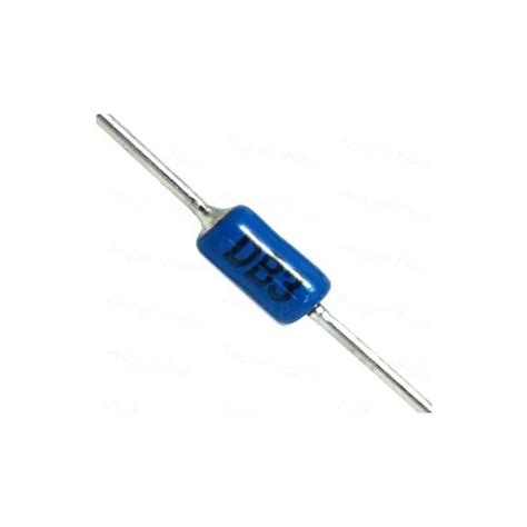
What is a DIAC?
A DIAC, or Diode for Alternating Current, is a two-terminal, Bidirectional Switching device that conducts current only after its breakover voltage has been reached momentarily. Once this threshold is reached, the DIAC continues to conduct until the current falls below the holding current. DIACs are widely used in AC power control applications, particularly in triggering TRIACs or SCRs in phase control circuits.
Construction of a DIAC
DIACs consist of three semiconductor layers arranged in a p-n-p or n-p-n configuration. They are symmetrical devices, meaning they can conduct current in both directions equally. The construction of a DIAC is similar to a transistor but without a base terminal. The symbol and equivalent circuit of a DIAC are shown below:
Characteristics of a DIAC
The key characteristics of a DIAC are:
- Breakover Voltage (VBO): The voltage at which the DIAC starts conducting. Typical values range from 20V to 36V.
- Breakover Current (IBO): The minimum current required to sustain conduction after the breakover voltage is reached. Typical values are around 50μA.
- Holding Current (IH): The minimum current required to maintain conduction. If the current falls below this value, the DIAC stops conducting. Typical values are around 10mA.
The typical I-V characteristics of a DIAC are shown below:
How does a DIAC work?
A DIAC has two stable states: high-resistance (off) and low-resistance (on). Initially, the DIAC is in its high-resistance state, blocking current flow. As the voltage across the DIAC increases, it reaches the breakover voltage (VBO). At this point, the DIAC rapidly transitions to its low-resistance state, allowing current to flow through it.
Once in the low-resistance state, the DIAC continues to conduct until the current through it drops below the holding current (IH). At this point, the DIAC returns to its high-resistance state, blocking current flow until the breakover voltage is reached again.
This behavior makes DIACs suitable for use in AC circuits, where they can conduct during both positive and negative half-cycles of the waveform.
Applications of DIACs
Phase Control Circuits
One of the primary applications of DIACs is in phase control circuits, where they are used to trigger TRIACs or SCRs. In these circuits, the DIAC acts as a voltage-sensitive switch, triggering the TRIAC or SCR at a specific point in the AC waveform. By controlling the triggering point, the power delivered to the load can be varied.
A typical phase control circuit using a DIAC and TRIAC is shown below:
In this circuit, the DIAC is connected between the gate and MT1 terminals of the TRIAC. The RC network (R1 and C1) determines the triggering point of the DIAC, and consequently, the firing angle of the TRIAC. By adjusting R1, the power delivered to the load can be controlled.
Dimmer Switches
DIACs are commonly used in dimmer switches for lighting control. In these applications, the DIAC-TRIAC combination is used to vary the power delivered to the lamp, allowing the brightness to be adjusted. A typical dimmer switch circuit using a DIAC and TRIAC is shown below:
Motor Speed Control
DIACs can also be used in motor speed control circuits, particularly for small AC motors. By varying the firing angle of the TRIAC using a DIAC, the power delivered to the motor can be controlled, thereby adjusting its speed. A simple motor speed control circuit using a DIAC and TRIAC is shown below:

Advantages and Disadvantages of DIACs
Advantages
- Simple and inexpensive
- Reliable triggering of TRIACs and SCRs
- Symmetrical construction allows bidirectional operation
- Compact size
Disadvantages
- Limited current handling capability
- Relatively high breakover voltage
- Not suitable for high-frequency applications
FAQ
1. What is the difference between a DIAC and a TRIAC?
A DIAC is a bidirectional switching device used primarily for triggering TRIACs or SCRs, while a TRIAC is a bidirectional switching device that can control the power delivered to a load directly. DIACs have a high off-state resistance and a low on-state resistance, whereas TRIACs have a low on-state voltage drop and can handle larger currents.
2. Can a DIAC be used without a TRIAC or SCR?
While DIACs are primarily used for triggering TRIACs or SCRs, they can be used independently in some applications, such as relaxation oscillators or simple switching circuits. However, their current handling capability is limited, and they are not suitable for directly controlling large loads.
3. What determines the breakover voltage of a DIAC?
The breakover voltage of a DIAC is determined by its internal structure, specifically the width of the depletion region and the doping levels of the semiconductor layers. The breakover voltage is typically specified in the DIAC’s datasheet and can range from 20V to 36V for commonly available devices.
4. How does the RC network in a DIAC-TRIAC phase control circuit affect the triggering point?
The RC network in a DIAC-TRIAC phase control circuit determines the voltage at which the DIAC will reach its breakover voltage and trigger the TRIAC. By adjusting the resistance value (R1), the charging time of the capacitor (C1) is varied, which in turn changes the point in the AC waveform at which the DIAC triggers the TRIAC. This allows the power delivered to the load to be controlled.
5. Are there any precautions to be taken when using DIACs in circuits?
When using DIACs in circuits, it is important to ensure that the maximum ratings specified in the datasheet are not exceeded. This includes the peak voltage, peak current, and average current ratings. Additionally, proper heat dissipation should be provided, especially in high-power applications, to prevent the DIAC from overheating and failing prematurely.


Leave a Reply