Introduction to the Arduino Mega2560
The Arduino Mega2560 is a powerful and versatile microcontroller board that has captured the hearts of makers, hobbyists, and professionals alike. With its sleek design and impressive capabilities, this board is not only functional but also undeniably cute and sexy. In this article, we will explore the features, specifications, and applications of the Arduino Mega2560, and discover why it has become a favorite among the Arduino community.
What is the Arduino Mega2560?
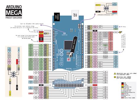
The Arduino Mega2560 is an open-source microcontroller board based on the ATmega2560 chip. It is an enhanced version of the Arduino Uno, offering more memory, more input/output pins, and additional features. This board is designed to handle complex projects that require more processing power and connectivity options.
| Feature | Arduino Mega2560 |
|---|---|
| Microcontroller | ATmega2560 |
| Operating Voltage | 5V |
| Input Voltage (recommended) | 7-12V |
| Input Voltage (limit) | 6-20V |
| Digital I/O Pins | 54 (of which 15 provide PWM output) |
| Analog Input Pins | 16 |
| DC Current per I/O Pin | 20 mA |
| DC Current for 3.3V Pin | 50 mA |
| Flash Memory | 256 KB (8 KB used by bootloader) |
| SRAM | 8 KB |
| EEPROM | 4 KB |
| Clock Speed | 16 MHz |
Why Choose the Arduino Mega2560?
There are several reasons why the Arduino Mega2560 has become a popular choice among makers and developers:
-
Enhanced Capabilities: With its increased memory and additional input/output pins, the Arduino Mega2560 enables users to create more complex projects and handle larger amounts of data.
-
Compatibility: The Arduino Mega2560 is compatible with most Arduino Shields and libraries, making it easy to integrate with existing projects and expand its functionality.
-
User-Friendly: Like other Arduino Boards, the Mega2560 is designed to be user-friendly and accessible to both beginners and experienced users. It comes with a comprehensive IDE (Integrated Development Environment) and a large community of users who share their knowledge and projects.
-
Versatility: The Arduino Mega2560 can be used for a wide range of applications, from robotics and home automation to data logging and interactive art installations.
Getting Started with the Arduino Mega2560
Setting Up the Development Environment
To start working with the Arduino Mega2560, you will need to set up the development environment on your computer. Follow these steps:
-
Download and install the Arduino IDE from the official Arduino website (https://www.arduino.cc/en/software).
-
Connect your Arduino Mega2560 board to your computer using a USB cable.
-
Open the Arduino IDE and select the correct board and port from the “Tools” menu.
-
You are now ready to start programming your Arduino Mega2560!
Basic Programming Concepts
Before diving into complex projects, it’s essential to understand some basic programming concepts in Arduino:
-
Setup() Function: This function is called once when the Arduino board starts up or is reset. It is used to initialize variables, set pin modes, and perform any other setup tasks.
-
Loop() Function: This function is called repeatedly after the setup() function has completed. It is the main body of your program where you define the behavior of your Arduino board.
-
Variables: Variables are used to store data in your program. Arduino supports various data types such as int, float, char, and boolean.
-
Functions: Functions are blocks of code that perform specific tasks. You can use built-in Arduino functions or create your own custom functions to modularize your code.
-
Libraries: Libraries are pre-written code packages that extend the functionality of your Arduino board. They provide additional features and simplify complex tasks.
Example Project: Blinking an LED
Let’s create a simple project to demonstrate the basic functionality of the Arduino Mega2560. In this example, we will blink an LED connected to one of the digital pins.
Hardware Requirements
- Arduino Mega2560 board
- Breadboard
- LED
- 220Ω resistor
- Jumper wires
Circuit diagram
         Arduino Mega2560
         +-----------+
         |           |
         |        13 |--+
         |           |  |
         +-----------+  |
                        |
                       +-+
                       | | LED
                       | |
                       +-+
                        |
                       +-+
                       | | 220Ω
                       | |
                       +-+
                        |
                       GND
Code
void setup() {
  pinMode(13, OUTPUT);  // Set pin 13 as an output
}

void loop() {
  digitalWrite(13, HIGH);  // Turn the LED on
  delay(1000);             // Wait for 1 second
  digitalWrite(13, LOW);   // Turn the LED off
  delay(1000);             // Wait for 1 second
}
In this code, we set pin 13 as an output in the setup() function. In the loop() function, we turn the LED on by setting the pin HIGH, wait for 1 second using the delay() function, then turn the LED off by setting the pin LOW, and wait for another second. This process repeats indefinitely, creating a blinking effect.

Advanced Applications of the Arduino Mega2560
Home Automation
The Arduino Mega2560 is an excellent choice for home automation projects due to its extensive input/output capabilities. You can connect various sensors and actuators to create a smart home system that can control lighting, temperature, security, and more.
Example: Smart Lighting Control
In this example, we will create a smart lighting system that automatically turns on the lights when it detects motion and turns them off after a certain period of inactivity.
Hardware Requirements
- Arduino Mega2560 board
- PIR motion sensor
- Relay module
- Jumper wires
Circuit Diagram
         Arduino Mega2560
         +-----------+
         |           |
         |         2 |--+-------> PIR motion sensor
         |           |  |
         |           |  |
         |         7 |--+-------> Relay module
         |           |
         +-----------+
Code
const int pirPin = 2;    // PIR motion sensor connected to pin 2
const int relayPin = 7;  // Relay module connected to pin 7
const int timeoutSeconds = 30;  // Timeout duration in seconds

int pirState = LOW;
int lastPirState = LOW;
unsigned long lastDetectionTime = 0;

void setup() {
  pinMode(pirPin, INPUT);
  pinMode(relayPin, OUTPUT);
  digitalWrite(relayPin, LOW);  // Turn off the lights initially
}

void loop() {
  pirState = digitalRead(pirPin);

  if (pirState == HIGH) {
    lastDetectionTime = millis();  // Update the last detection time
    digitalWrite(relayPin, HIGH);  // Turn on the lights
  }

  if ((millis() - lastDetectionTime) > (timeoutSeconds * 1000)) {
    digitalWrite(relayPin, LOW);  // Turn off the lights after timeout
  }

  lastPirState = pirState;
  delay(100);
}
In this code, we use a PIR motion sensor to detect motion and a relay module to control the lights. When motion is detected, the relay is activated to turn on the lights, and the last detection time is updated. If no motion is detected for the specified timeout duration (30 seconds in this example), the lights are turned off.
Robotics
The Arduino Mega2560 is a popular choice for robotics projects due to its ample input/output pins and processing power. You can use it to control motors, sensors, and other components to create autonomous or remote-controlled robots.
Example: Line-Following Robot
In this example, we will create a line-following robot that uses infrared sensors to detect and follow a black line on a white surface.
Hardware Requirements
- Arduino Mega2560 board
- 2 DC motors with wheels
- L298N motor driver module
- 2 IR line sensors
- Jumper wires
Circuit Diagram
         Arduino Mega2560
         +-----------+
         |           |
         |         4 |--+-------> IR sensor 1
         |         5 |--+-------> IR sensor 2
         |           |
         |         7 |--+-------> Motor driver IN1
         |         8 |--+-------> Motor driver IN2
         |         9 |--+-------> Motor driver IN3
         |        10 |--+-------> Motor driver IN4
         |           |
         +-----------+

         L298N Motor Driver
         +-----------+
         |           |
         |  IN1  OUT1|-------> Motor 1 +
         |  IN2  OUT2|-------> Motor 1 -
         |  IN3  OUT3|-------> Motor 2 +
         |  IN4  OUT4|-------> Motor 2 -
         |           |
         +-----------+
Code
const int irSensor1 = 4;  // IR sensor 1 connected to pin 4
const int irSensor2 = 5;  // IR sensor 2 connected to pin 5

const int motorPin1 = 7;  // Motor driver IN1 connected to pin 7
const int motorPin2 = 8;  // Motor driver IN2 connected to pin 8
const int motorPin3 = 9;  // Motor driver IN3 connected to pin 9
const int motorPin4 = 10;  // Motor driver IN4 connected to pin 10

void setup() {
  pinMode(irSensor1, INPUT);
  pinMode(irSensor2, INPUT);
  pinMode(motorPin1, OUTPUT);
  pinMode(motorPin2, OUTPUT);
  pinMode(motorPin3, OUTPUT);
  pinMode(motorPin4, OUTPUT);
}

void loop() {
  int sensorValue1 = digitalRead(irSensor1);
  int sensorValue2 = digitalRead(irSensor2);

  if (sensorValue1 == LOW && sensorValue2 == LOW) {
    // Both sensors detect the line, move forward
    moveForward();
  } else if (sensorValue1 == LOW && sensorValue2 == HIGH) {
    // Left sensor detects the line, turn left
    turnLeft();
  } else if (sensorValue1 == HIGH && sensorValue2 == LOW) {
    // Right sensor detects the line, turn right
    turnRight();
  } else {
    // No line detected, stop the motors
    stopMotors();
  }
}

void moveForward() {
  digitalWrite(motorPin1, HIGH);
  digitalWrite(motorPin2, LOW);
  digitalWrite(motorPin3, HIGH);
  digitalWrite(motorPin4, LOW);
}

void turnLeft() {
  digitalWrite(motorPin1, LOW);
  digitalWrite(motorPin2, HIGH);
  digitalWrite(motorPin3, HIGH);
  digitalWrite(motorPin4, LOW);
}

void turnRight() {
  digitalWrite(motorPin1, HIGH);
  digitalWrite(motorPin2, LOW);
  digitalWrite(motorPin3, LOW);
  digitalWrite(motorPin4, HIGH);
}

void stopMotors() {
  digitalWrite(motorPin1, LOW);
  digitalWrite(motorPin2, LOW);
  digitalWrite(motorPin3, LOW);
  digitalWrite(motorPin4, LOW);
}
In this code, we use two IR sensors to detect the presence of a black line on a white surface. Based on the sensor readings, the robot moves forward, turns left, turns right, or stops. The motor driver module is used to control the DC motors and provide the necessary power to drive the wheels.

Frequently Asked Questions (FAQ)
- Q: What is the difference between the Arduino Mega2560 and the Arduino Uno?
A: The main differences between the Arduino Mega2560 and the Arduino Uno are: - The Mega2560 has more input/output pins (54 digital pins and 16 analog pins) compared to the Uno (14 digital pins and 6 analog pins).
- The Mega2560 has a larger memory capacity (256 KB flash memory, 8 KB SRAM, 4 KB EEPROM) compared to the Uno (32 KB flash memory, 2 KB SRAM, 1 KB EEPROM).
-
The Mega2560 is physically larger than the Uno due to its increased capabilities.
-
Q: Can I use Arduino shields designed for the Uno with the Mega2560?
A: Yes, most Arduino shields designed for the Uno are compatible with the Mega2560. However, it’s always a good idea to check the shield’s documentation or specifications to ensure compatibility. -
Q: How do I power the Arduino Mega2560?
A: You can power the Arduino Mega2560 using a USB cable connected to your computer or an external power supply. The recommended input voltage range is 7-12V, but the board can accept voltages between 6-20V. Keep in mind that higher voltages may generate more heat and potentially damage the board. -
Q: What programming language is used to program the Arduino Mega2560?
A: The Arduino Mega2560 is programmed using a simplified version of C++. The Arduino IDE provides an easy-to-use environment for writing, compiling, and uploading code to the board. -
Q: Can I use the Arduino Mega2560 for commercial projects?
A: Yes, you can use the Arduino Mega2560 for commercial projects. The Arduino platform is open-source, which means you are free to use, modify, and distribute the hardware and software for commercial purposes. However, it’s important to comply with the Arduino trademark guidelines if you plan to use the Arduino name or logo in your products.

Conclusion
The Arduino Mega2560 is a powerful and attractive microcontroller board that offers endless possibilities for makers, hobbyists, and professionals. With its enhanced capabilities, compatibility, and user-friendly nature, it has become a go-to choice for a wide range of projects, from home automation to robotics and beyond.
In this article, we explored the features and specifications of the Arduino Mega2560, learned how to set up the development environment, and walked through basic programming concepts. We also delved into advanced applications, such as home automation and robotics, and provided example projects to demonstrate the board’s versatility.
Whether you’re a beginner looking to get started with Arduino or an experienced user seeking to take your projects to the next level, the Arduino Mega2560 is a reliable and cute companion that will help bring your ideas to life. So go ahead, embrace your creativity, and unleash the potential of this sexy barebones board!


Leave a Reply