Introduction to Arduino Leonardo
The Arduino Leonardo is a popular microcontroller board based on the ATmega32u4 chip. It offers a variety of features and capabilities that make it an excellent choice for both beginners and experienced makers alike. In this article, we will take an in-depth look at the Arduino Leonardo Pinout, exploring the various connection points and their functions.
Overview of the ATmega32u4 Microcontroller
At the heart of the Arduino Leonardo lies the ATmega32u4 microcontroller. This powerful chip is responsible for executing the code and managing the board’s various input and output pins. The ATmega32u4 offers the following features:
- 32 KB of flash memory for storing code
- 2.5 KB of SRAM for temporary data storage
- 1 KB of EEPROM for persistent data storage
- 20 MHz clock speed
- USB 2.0 support for programming and communication

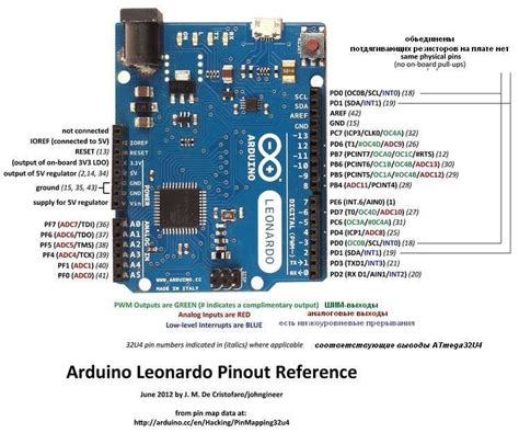
Arduino Leonardo Pinout Diagram
To better understand the Arduino Leonardo’s pinout, let’s take a look at the board’s diagram:

Digital I/O Pins
The Arduino Leonardo features 20 digital input/output (I/O) pins, labeled 0 to 13 and A0 to A5. These pins can be used for various purposes, such as:
- Reading digital inputs (e.g., buttons, switches)
- Controlling digital outputs (e.g., LEDs, relays)
- Implementing serial communication protocols (e.g., UART, SPI, I2C)
Here’s a table summarizing the digital I/O pins and their additional functions:
| Pin | Function |
|---|---|
| 0 | RX (UART) |
| 1 | TX (UART) |
| 2 | SDA (I2C) |
| 3 | SCL (I2C) |
| 4 | Digital I/O, |
Continued
| Pin | Function |
|---|---|
| 5 | PWM Digital I/O |
| 6 | PWM Digital I/O |
| 7 | Digital I/O |
| 8 | Digital I/O, SS (SPI) |
| 9 | PWM Digital I/O, MOSI (SPI) |
| 10 | PWM Digital I/O, MISO (SPI) |
| 11 | PWM Digital I/O, SCK (SPI) |
| 12 | Digital I/O, MISO (SPI) |
| 13 | Built-in LED, SCK (SPI) |
| A0 | Analog Input |
| A1 | Analog Input |
| A2 | Analog Input |
| A3 | Analog Input |
| A4 | Analog Input, SDA (I2C) |
| A5 | Analog Input, SCL (I2C) |

Analog Input Pins
The Arduino Leonardo has 6 analog input pins, labeled A0 to A5. These pins can measure analog voltage levels between 0V and 5V, with a resolution of 10 bits (1024 discrete values). Analog inputs are commonly used for reading sensors that output varying voltage levels, such as potentiometers, light sensors, and temperature sensors.
PWM Pins
Among the digital I/O pins, 7 pins (3, 5, 6, 9, 10, 11, and 13) are capable of pulse-width modulation (PWM). PWM is a technique used to simulate analog output by rapidly toggling a digital pin on and off. This is useful for controlling the brightness of LEDs, the speed of motors, or generating audio signals.
Communication Interfaces
The Arduino Leonardo supports several communication protocols through its digital pins:
UART (Serial)
- Pin 0 (RX): Receive data
- Pin 1 (TX): Transmit data
UART is a standard serial communication protocol used for exchanging data between the Arduino and other devices, such as computers, GPS modules, or Bluetooth modules.
I2C
- Pin 2 (SDA): Data line
- Pin 3 (SCL): Clock line
I2C is a two-wire interface that allows the Arduino to communicate with multiple devices using just two pins. It’s commonly used for connecting sensors, displays, and memory devices.
SPI
- Pin 8 (SS): Slave Select
- Pin 9 (MOSI): Master Out, Slave In
- Pin 10 (MISO): Master In, Slave Out
- Pin 11 (SCK): Clock signal
SPI is a high-speed synchronous serial protocol used for communicating with peripherals such as sensors, displays, and SD cards. It requires four pins and allows for faster data transfer rates compared to I2C.
Power Pins
The Arduino Leonardo has several pins dedicated to power supply and ground:
- VIN: Input voltage (7-12V)
- 5V: Regulated 5V output
- 3.3V: Regulated 3.3V output
- GND: Ground
These pins are used for powering the board and any connected peripherals. The VIN pin can accept an external power supply between 7V and 12V, while the 5V and 3.3V pins provide regulated power outputs for components that require stable voltage levels.
Reset Pin
The Arduino Leonardo has a dedicated reset pin that can be used to restart the microcontroller. Pulling this pin LOW will trigger a reset, which is equivalent to pressing the on-board reset button.
USB Interface
One of the key features of the Arduino Leonardo is its built-in USB interface. The ATmega32u4 microcontroller has native USB support, allowing the board to appear as a generic keyboard or mouse to a connected computer. This enables the creation of custom human interface devices (HIDs) without the need for additional hardware.
The USB interface is also used for programming the board and for serial communication with the computer. When connected via USB, the Arduino Leonardo appears as a virtual COM port, allowing you to send and receive data using the Arduino IDE’s serial monitor or other serial communication software.
Connecting Peripherals to the Arduino Leonardo
Now that we’ve explored the various pins and interfaces available on the Arduino Leonardo, let’s look at some examples of how to connect common peripherals to the board.
Connecting an LED
To connect an LED to the Arduino Leonardo, you’ll need:
– An LED
– A 220Ω resistor
– Jumper wires
Follow these steps:
1. Connect the cathode (shorter leg) of the LED to a 220Ω resistor.
2. Connect the other end of the resistor to one of the digital I/O pins (e.g., pin 13).
3. Connect the anode (longer leg) of the LED to the 5V pin.
Here’s a simple code example to blink the LED:
void setup() {
  pinMode(13, OUTPUT);
}

void loop() {
  digitalWrite(13, HIGH);
  delay(1000);
  digitalWrite(13, LOW);
  delay(1000);
}
Connecting a Button
To connect a button to the Arduino Leonardo, you’ll need:
– A pushbutton
– A 10kΩ resistor
– Jumper wires
Follow these steps:
1. Connect one leg of the button to a digital I/O pin (e.g., pin 2).
2. Connect the other leg of the button to GND.
3. Connect a 10kΩ resistor between the digital I/O pin and 5V (pull-up resistor).
Here’s a simple code example to read the button state:
void setup() {
  pinMode(2, INPUT_PULLUP);
  Serial.begin(9600);
}

void loop() {
  int buttonState = digitalRead(2);
  Serial.println(buttonState);
  delay(100);
}
Connecting an I2C Sensor
To connect an I2C sensor (e.g., an MPU-6050 accelerometer/gyroscope) to the Arduino Leonardo, you’ll need:
– The I2C sensor
– Jumper wires
Follow these steps:
1. Connect the sensor’s VCC pin to the Arduino’s 3.3V or 5V pin (depending on the sensor’s voltage requirement).
2. Connect the sensor’s GND pin to the Arduino’s GND pin.
3. Connect the sensor’s SDA pin to the Arduino’s SDA pin (A4).
4. Connect the sensor’s SCL pin to the Arduino’s SCL pin (A5).
Here’s a simple code example using the MPU6050 library:
#include <Wire.h>
#include <MPU6050.h>

MPU6050 mpu;

void setup() {
  Serial.begin(9600);
  Wire.begin();
  mpu.initialize();
}

void loop() {
  int16_t ax, ay, az, gx, gy, gz;
  mpu.getMotion6(&ax, &ay, &az, &gx, &gy, &gz);
  Serial.print("Accelerometer: ");
  Serial.print(ax); Serial.print(", ");
  Serial.print(ay); Serial.print(", ");
  Serial.println(az);
  Serial.print("Gyroscope: ");
  Serial.print(gx); Serial.print(", ");
  Serial.print(gy); Serial.print(", ");
  Serial.println(gz);
  delay(100);
}
Frequently Asked Questions (FAQ)
1. Can I use the Arduino Leonardo with 3.3V sensors and peripherals?
Yes, the Arduino Leonardo has a built-in 3.3V regulator that can provide power to 3.3V devices. However, keep in mind that the I/O pins still operate at 5V, so you may need to use level shifters or voltage dividers to interface with 3.3V devices safely.
2. How many analog inputs does the Arduino Leonardo have?
The Arduino Leonardo has 6 analog input pins, labeled A0 to A5. These pins can measure analog voltage levels between 0V and 5V with a resolution of 10 bits (1024 discrete values).
3. Can I use the Arduino Leonardo as a USB keyboard or mouse?
Yes, the Arduino Leonardo’s ATmega32u4 microcontroller has native USB support, allowing the board to appear as a generic keyboard or mouse to a connected computer. This feature enables the creation of custom human interface devices (HIDs) without additional hardware.
4. What is the difference between the Arduino Leonardo and the Arduino Uno?
The main difference between the Arduino Leonardo and the Arduino Uno lies in their microcontrollers. The Leonardo uses the ATmega32u4, which has built-in USB support, while the Uno uses the ATmega328P and requires a separate USB-to-serial chip. Additionally, the Leonardo has fewer analog input pins (6) compared to the Uno (8), and the pin layout is slightly different.
5. Can I power the Arduino Leonardo using a battery?
Yes, you can power the Arduino Leonardo using a battery by connecting it to the VIN pin. The board can accept an input voltage between 7V and 12V. Alternatively, you can power the board through the USB port, which provides a regulated 5V supply.
Conclusion
The Arduino Leonardo is a versatile microcontroller board that offers a wide range of connection options through its ATmega32u4 chip. By understanding the board’s pinout and the functions of each pin, you can easily interface with various sensors, actuators, and communication modules to create engaging projects.
Whether you’re a beginner or an experienced maker, the Arduino Leonardo provides a solid foundation for exploring the world of electronics and programming. With its native USB support and extensive library ecosystem, the possibilities for creating innovative projects are endless.


Leave a Reply