Introduction to AM Receiver Circuits
An AM (Amplitude Modulation) receiver circuit is a type of radio receiver that detects and demodulates amplitude-modulated radio signals. AM radio broadcasting has been a popular means of communication for decades, and understanding how an AM receiver works is essential for anyone interested in electronics and radio technology.
In this article, we will explore the fundamentals of AM receiver circuits, their components, and how they function together to receive and process AM radio signals. Additionally, we will guide you through the process of building a simple AM receiver circuit project, allowing you to experience the technology firsthand.
What is an AM Receiver Circuit?
An AM receiver circuit is designed to detect and demodulate amplitude-modulated radio signals. AM radio signals consist of a carrier wave whose amplitude is varied in proportion to the audio signal being transmitted. The receiver circuit’s primary goal is to extract the original audio signal from the modulated carrier wave.
Components of an AM Receiver Circuit
A basic AM receiver circuit consists of several essential components:
- Antenna
- RF (Radio Frequency) Amplifier
- Local Oscillator
- Mixer
- IF (Intermediate Frequency) Amplifier
- Detector
- Audio Amplifier
Each component plays a crucial role in the overall functioning of the AM receiver circuit.
How an AM Receiver Circuit Works
Signal Reception and RF Amplification
The AM receiver circuit begins with the antenna, which captures the incoming AM radio signals. The antenna converts the electromagnetic waves into electrical signals, which are then fed into the RF amplifier.
The RF amplifier boosts the weak signal received by the antenna, increasing its strength and filtering out unwanted frequencies. This stage helps to improve the signal-to-noise ratio and prepares the signal for further processing.
Frequency Conversion and IF Amplification
The amplified RF signal is then mixed with a signal generated by the local oscillator in the mixer stage. The local oscillator produces a signal with a frequency that is slightly different from the desired AM signal frequency. The mixer combines these two signals, resulting in the creation of two new frequencies: the sum and difference of the original frequencies.
The difference frequency, known as the intermediate frequency (IF), is selected using a bandpass filter. The IF signal is then amplified by the IF amplifier stage, which further increases the signal strength and filters out any remaining unwanted frequencies.
Detection and Audio Amplification
The amplified IF signal is then sent to the detector stage, which is responsible for extracting the original audio signal from the modulated carrier wave. The most common type of detector used in AM receiver circuits is the envelope detector, which consists of a diode and a capacitor.
The envelope detector removes the high-frequency carrier wave, leaving behind the audio signal. This audio signal is then amplified by the audio amplifier stage, making it suitable for driving a speaker or headphones.

Building a Simple AM Receiver Circuit Project
Now that we have a basic understanding of how an AM receiver circuit works, let’s build a simple project to experience it firsthand.
Required Components
- Ferrite rod antenna
- Variable capacitor (20-200 pF)
- Germanium diode (1N34A or equivalent)
- 100 kΩ resistor
- 47 nF capacitor
- 100 nF capacitor
- 10 kΩ potentiometer
- LM386 audio amplifier IC
- 8Ω speaker
- 9V battery and connector
- Breadboard and jumper wires
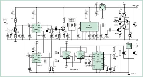
Circuit Diagram
[Insert a clear circuit diagram of the simple AM receiver project]
Step-by-Step Instructions
-
Begin by placing the ferrite rod antenna on the breadboard. Connect one end of the antenna to the variable capacitor and the other end to ground.
-
Connect the other terminal of the variable capacitor to the anode of the germanium diode. The diode’s cathode should be connected to one end of the 100 kΩ resistor.
-
Connect the other end of the 100 kΩ resistor to the positive rail of the breadboard. Place the 47 nF capacitor between the diode’s cathode and ground.
-
Connect the diode’s cathode to the input (pin 3) of the LM386 audio amplifier IC. Connect pin 2 of the LM386 to ground.
-
Place the 100 nF capacitor between pins 1 and 8 of the LM386. Connect pin 7 to the positive rail and pin 4 to ground.
-
Connect one end of the 10 kΩ potentiometer to pin 1 of the LM386, the other end to ground, and the wiper to pin 8.
-
Connect the positive terminal of the 8Ω speaker to pin 5 of the LM386, and the negative terminal to ground.
-
Finally, connect the positive terminal of the 9V battery to the positive rail and the negative terminal to ground.
Testing and Tuning
-
Double-check all connections to ensure they are correct and secure.
-
Turn on the power supply (9V battery) and slowly adjust the variable capacitor until you hear a clear AM radio station through the speaker.
-
Fine-tune the variable capacitor for the best reception and use the 10 kΩ potentiometer to adjust the volume to a comfortable level.
Congratulations! You have now built a simple AM receiver circuit and experienced the process of receiving and demodulating AM radio signals.

Frequently Asked Questions (FAQ)
-
Q: What is the purpose of the ferrite rod antenna in the AM receiver circuit?
A: The ferrite rod antenna is used to capture the incoming AM radio signals and convert them into electrical signals that can be processed by the receiver circuit. -
Q: Why is a germanium diode used in the simple AM receiver project instead of a silicon diode?
A: Germanium diodes have a lower forward voltage drop compared to silicon diodes, which makes them more suitable for detecting weak AM radio signals in simple receiver circuits. -
Q: Can I use a different audio amplifier IC instead of the LM386?
A: Yes, you can use other audio amplifier ICs, such as the TDA2822 or the TBA820M, as long as they are compatible with the circuit design and can provide sufficient amplification for the speaker. -
Q: What is the purpose of the variable capacitor in the AM receiver circuit?
A: The variable capacitor is used for tuning the receiver circuit to the desired AM radio station frequency. By adjusting the capacitance, you can change the resonant frequency of the LC tank circuit formed by the ferrite rod antenna and the variable capacitor. -
Q: Can I make this AM receiver circuit more sensitive to weaker radio signals?
A: To improve the sensitivity of the AM receiver circuit, you can try using a larger ferrite rod antenna, increasing the number of turns on the antenna coil, or adding an additional RF amplification stage before the detector stage.

Conclusion
In this article, we have explored the fundamentals of AM receiver circuits, their components, and how they work together to receive and demodulate AM radio signals. We have also provided a step-by-step guide to building a simple AM receiver circuit project, allowing you to experience the technology firsthand.
Understanding AM receiver circuits is an essential step in learning about radio technology and electronics. By building this simple project, you have gained valuable hands-on experience and a deeper appreciation for the ingenious design of these circuits.
As you continue to explore the world of electronics and radio technology, you can build upon this knowledge to create more advanced projects and delve deeper into the fascinating field of wireless communication.


Leave a Reply