The popularity of rigid-flex printed circuit boards (PCBs) has grown tremendously over the past decade. Rigid-flex PCBs provide a compact and lightweight solution for electronic devices where flexibility is required alongside strength and stability. This guidebook aims to provide designers and engineers with a comprehensive overview of rigid-flex PCBs and how to design them using Altium Designer.
What are Rigid-Flex PCBs?
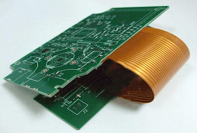
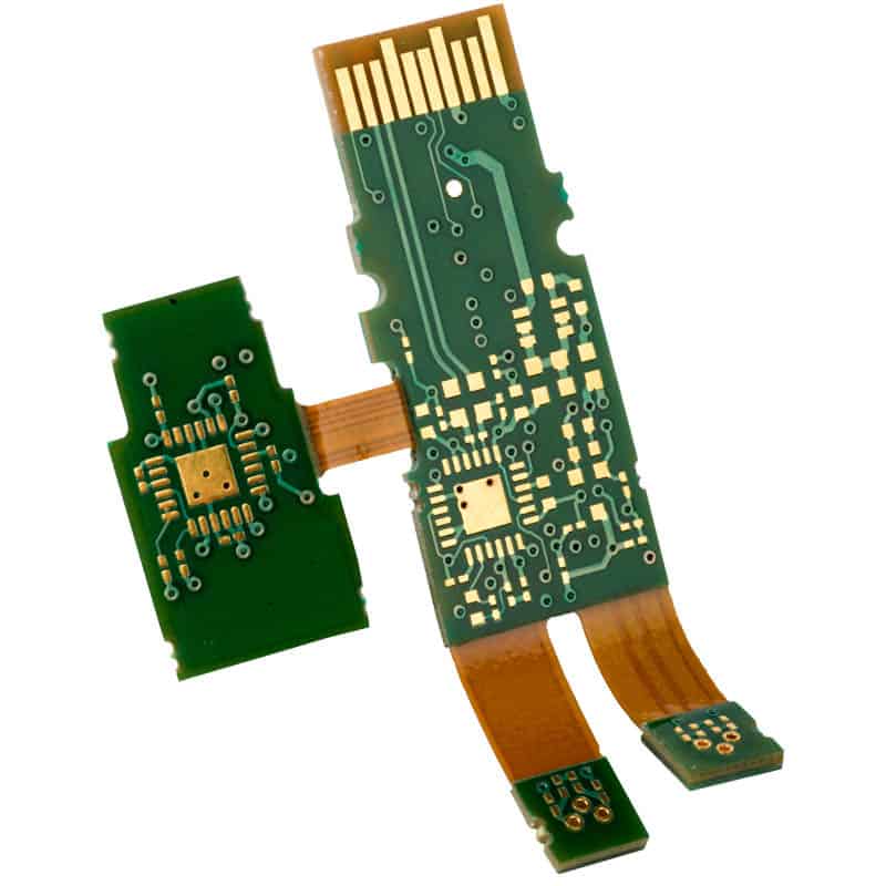
Rigid-flex PCBs integrate both rigid and flexible substrate layers into a single circuit assembly. They contain rigid sections for components and connectors along with flexible sections that allow dynamic flexing, folding or wrapping around structures. The rigid sections provide mechanical support while the flexible sections enable movement and adaptability.
Key benefits of rigid-flex PCBs:
- Compact, space saving design
- Ability to fit into and adapt to challenging spaces
- Flexible sections allow motion and reconfiguration
- Can be curved, folded or twisted while maintaining circuit integrity
- Lightweight and durable compared to alternatives
- Can eliminate connectors between separate rigid PCBs
Rigid-flex is suitable for products like cameras, wearables, medical devices, aerospace avionics and consumer electronics. They are often used when products need to meet both electrical and mechanical requirements.
Materials for Rigid-Flex PCBs
The materials used in rigid-flex PCBs include:
Rigid Substrates
- FR-4 – Most common rigid substrate, made of woven fiberglass cloth with an epoxy resin binder
- High-Tg FR-4 – Improved thermal performance for high temp applications
- Halogen-free substrates – Used for environmental compliance
- High-speed materials – Low dielectric loss, tightly controlled impedance
Flexible Substrates
- Polyimide – Most common flex material, high temperature resistance
- PEN polyester – Lower cost alternative to polyimide
- Fluoropolymer films – Extremely high temp resistance
Bondply materials are also used which integrate flexible polyimide between two outer layers of FR-4.
Coverlay Materials
Coverlay or solder mask layers are applied to both sides of the finished rigid-flex assembly for protection and insulation. Common options include:
- Liquid photoimageable solder mask (LPI)
- Dry film solder mask
- Flexible solder mask – Provides bendability
- Conformal coatings – Paralyne, urethane, acrylic, silicone
Rigid-Flex Design Guidelines
Here are some key guidelines to follow when designing rigid-flex PCBs in Altium:
Layer Stackup
- Plan number of layers needed for trace routing upfront
- Use symmetric construction for easier assembly and improved reliability
- Controlled impedances require prepreg/bondply thickness of 2-4 mils per layer
- Minimize number of different materials used
Board Outline
- Use smooth curves for flex-to-rigid transitions – minimum bend radius of 10X material thickness
- Avoid sharp corners to reduce stress points
- Place rigids symmetrically around neutral axis for uniform stretch/compression
Component Placement
- Minimize component density in flex sections
- Avoid placing small passive parts in flex areas
- Plan ahead for stiffener/support placement
Trace Routing
- Use comb pattern for traces traversing flex sections
- Minimize trace lengths in bend areas
- Set teardrop pads to relieve solder joint stress
- Limit minimum bend radius to 10X board thickness
Vias
- Avoid vias in dynamic flex zones
- Backdrill unused section of any plated through-hole vias
- Use stacked and filled vias for reliability
Testing
- Perform fold cycle testing to validate flex endurance
- Dynamic flex testing prior to production
- Controlled impedance testing
Designing Rigid-Flex PCBs in Altium
Altium Designer provides dedicated features and functionality for designing complex rigid-flex PCBs. Here are some key steps in the design process:
Layer Stack Management
The Layer Stack Manager lets you create layer stacks with different materials used in the rigid and flex sections. This defines the layer order, substrates, and materials.
Defining Rigid-Flex Regions
The Rigid-Flex Editor is used to define the board outline and place rigid and flex region polygons. The constraints defined here control trace routing and visibility.
Routing Traces
The interactive routing modes allow traces to smoothly transition between rigid and flex layers. Teardrops can be automatically added to pad entries.
3D Modeling
The board shape can be folded and modeled in 3D to validate the design before manufacturing. The flex and motion capabilities can be visualized.
Generating Fabrication Data
The outputs for rigid-flex projects are more complex. Separate files may be needed for each section. The manufacturing documentation can be directly generated.
Key Considerations for Rigid-Flex PCBs
Electrical Rules
Follow the same circuit and PCB design principles used for rigid boards. Take special care with:
- Controlled impedance requirements
- High-speed signals crossing bends
- Effects of dynamic flexing on conductors
Mechanical Structures
The mechanical features provide physical support:
- Stiffeners and frames to constrain flexible sections
- Strategic placement of components and connectors
- Guides or rails for slide mechanisms
Manufacturing and Assembly
Work closely with your fabricator to ensure:
- Their capabilities match your design
- The layer stackup and materials are all supported
- Fr4 and flex layers are properly aligned and bonded
- Surface finishes are compatible
- Careful handling to avoid damage
Rigid-Flex Design Examples
Here are two examples of products using rigid-flex PCBs:
Wearable Health Monitor
This wrist-worn device monitors vital health metrics using advanced sensors. A rigid board hosts the main processor, memory, and power supply. Flexible interconnects extend to sensor modules that conform to the user’s body. The narrow interconnects enable the compact, ergonomic design.
Drone Gimbal Assembly
This 3-axis drone gimbal mounts the camera to the undercarriage and enables smooth video footage and photography. The rigid sections hold the gyro sensors, controllers and camera slot. The flexible sections allow 220 degrees of tilt and 60 degrees of roll and pan.
Frequently Asked Questions
Here are some common questions about rigid-flex PCB design:
What are the typical layer counts for rigid-flex boards?
Rigid layers are typically 2-8 layers or more. Flex layers are often 2-4 layers. High layer counts are possible but increase complexity and cost.
What are recommended minimum bend radii?
The minimum bend radius should be at least 10X the total board thickness. Some flex materials or high layer counts require larger radii of 20X or more.
Can off-the-shelf rigid-flex PCBs be purchased?
Yes, companies like Flexible Circuit Technologies offer off-the-shelf rigid-flex products. However, custom designs allow optimization and typically offer the lowest cost at high volumes.
What design software is best for rigid-flex boards?
Altium Designer provides dedicated rigid-flex design features for layer stacks, routing, 3D modeling and manufacturing outputs. Cadence and Mentor Graphics also support rigid-flex workflows.
How are components assembled on rigid-flex boards?
Soldering to rigid sections can use standard SMT and through-hole assembly. Flex sections allow only SMT parts with flex-compatible adhesives. Press-fit connectors avoid hand soldering.
Conclusion
Rigid-flex PCB technology enables products that are compact, lightweight and able to integrate both rigid and dynamic flexing requirements. Rigid sections provide stability for components while flex sections allow motion and three-dimensional configurations. With an understanding of the materials, layout considerations and manufacturing factors involved, electronics design teams can take full advantage of the benefits of rigid-flex using solutions like Altium Designer. The result is tightly integrated, high reliability products.


Leave a Reply