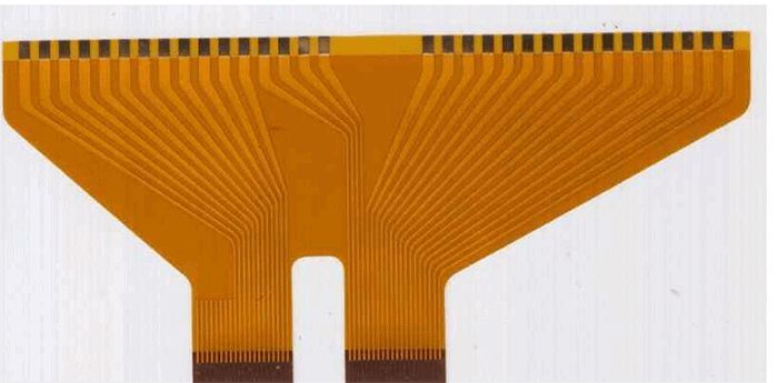
Rigid-flex printed circuit boards (PCBs) combine rigid and flexible substrates to allow connections between multiple rigid sections of a circuit while still allowing flexible movement. The flexible sections, called “flex” for short, enable new possibilities for 3D circuit routing and more compact product designs. However, the abrupt transition between rigid and flex areas leads to mechanical challenges that must be addressed through careful PCB design techniques. One important technique is to reinforce the rigid-flex interface with stiffeners on the flex layers. Altium provides dedicated flex stiffener tools to automate and streamline this process.
What Are Flex Stiffeners?

A flex stiffener is an additional layer of stiff reinforcement material added in the flex area, right up to the interface with the rigid section. Common stiffener materials include coverlay, bondply, and copper. The stiffener prevents unwanted flexing at the rigid-flex junction and provides mechanical stability. It acts as a buffer to reduce shear and peel stresses on the flex layers during movement.
Without stiffeners, the thin flexible layers would be likely to develop cracks over time as the materials are fatigued through repeated motion. Stiffeners enhance reliability and extend the functional lifetime of rigid-flex designs.
Benefits of Using Altium Flex Stiffeners
Altium’s PCB design software provides dedicated tools for creating and managing flex stiffeners as part of the rigid-flex design process:
- Automated stiffener generation based on rigid-flex layer stackup
- Adjustable stiffener backer length on each layer
- Support for different stiffener types per layer
- Full integration with rigid-flex coverlay shapes
- Length tuning to control stiffness graduations
- Edits are updated automatically across layers
The automated stiffener generation ensures correct placement and alignment across all layers. Designers can specify the required stiffener type for each layer independently. Adjustments to the stiffener lengths are applied automatically to all layers, providing consistent graduations in the transition areas.
How to Add Flex Stiffeners in Altium
Adding stiffeners in Altium involves three key steps:
- Define rigid-flex layer stackup – The layer stack manager is used to define the layer order, including flexible layers, coverlay, and bondply. The software understands the relationships between layers.
- Generate stiffeners – The stiffener generator is used to automatically create stiffeners on all appropriate layers. The length can be specified and is mirrored on all layers.
- Tune stiffener lengths – The length of individual stiffeners can be “tuned” to create graduated stiffness across the flexible region. Length changes propagate between layers automatically.
Here is a simple example layer stack and stiffener setup:
| Layer | Type | Stiffener |
|---|---|---|
| Top Layer | Rigid | None |
| Top Coverlay | Flex | Full Length |
| Signal 1 | Flex | Full Length |
| Signal 2 | Flex | Full Length |
| Bondply 1 | Stiffener | Full Length |
| Signal 3 | Flex | Full Length |
| Signal 4 | Flex | Full Length |
| Bottom Coverlay | Flex | Full Length |
| Bottom Layer | Rigid | None |
And here are the steps to generate and tune the stiffeners for this stackup in Altium:
- Define the layer stack with coverlay, bondply, and flexible signal layers
- Generate stiffeners on coverlay and bondply layers
- Reduce length of bottom coverlay stiffener to create graduation
- Changes propagate automatically to bondply stiffener
The generated stiffeners provide reinforcement right up to the rigid-flex junction. The graduated lengths help relieve shear stress and prevent delamination.
Applying Gridded and Serpentine Flex Stiffeners

In addition to generating rectangular stiffeners, Altium provides advanced options for creating gridded or serpentine stiffener shapes.
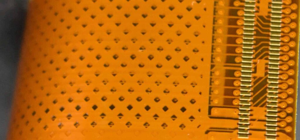
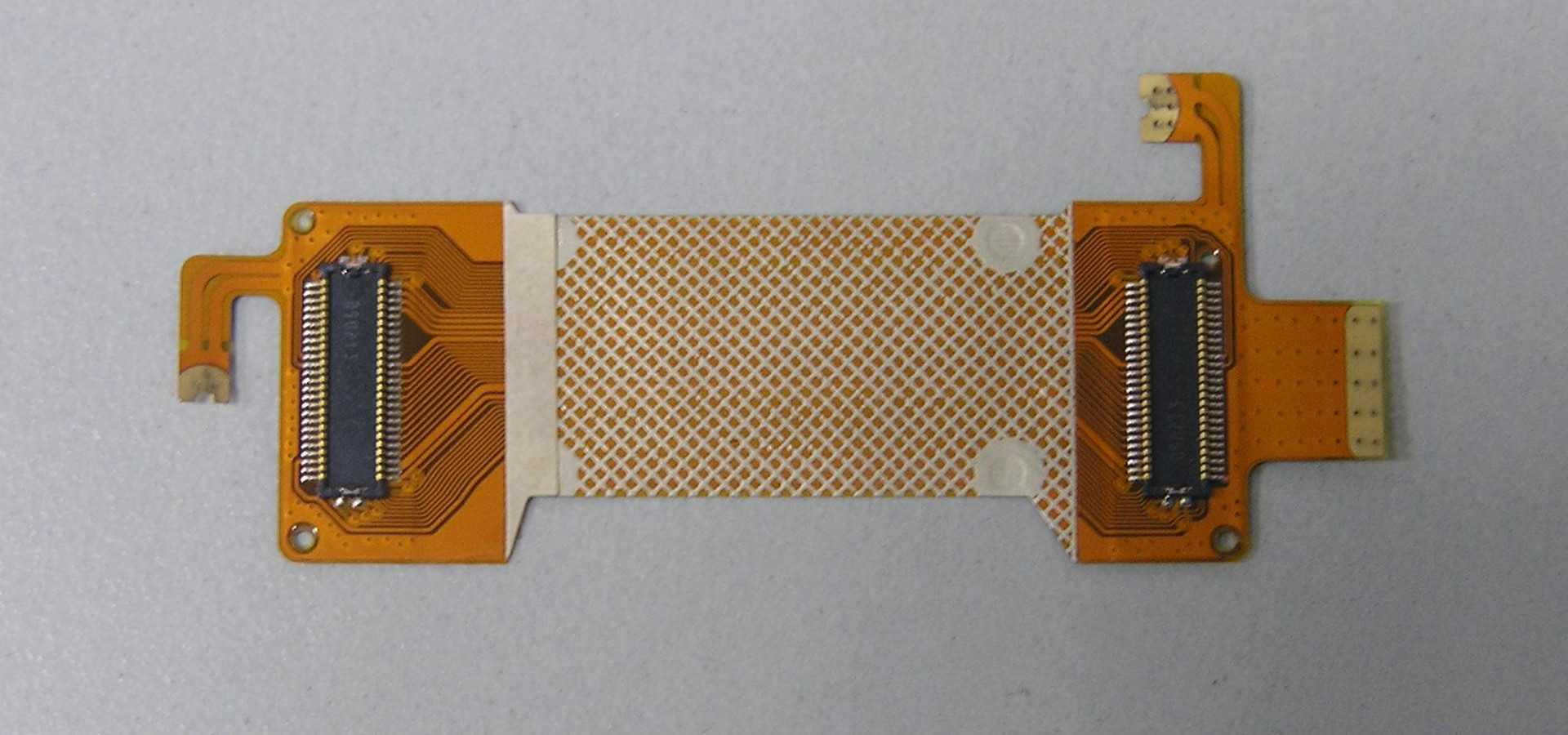
Gridded stiffeners add a pattern of small rectangle pads, like a mesh grid, as the stiffener layer. This helps reduce stiffness somewhat compared to a solid shape. Grid spacing and pad size can be configured.
Serpentine stiffeners use a meandering trace pattern rather than a solid shape. This allows high stiffness reinforcement while retaining some flexibility. Serpentine parameters like amplitude and number of cycles can be tuned.
The gridded or serpentine stiffeners can be generated on the bondply/coverlay layers. Adjustments will propagate to create matching patterns on paired layers for symmetry. These options provide an extra degree of control over the tradeoff between flexibility and rigidity in the flex area.
Controlling Flex Stiffness with Copper Balancing
In addition to adding dedicated stiffener layers, stiffness in the flex region can be controlled through careful copper balancing. This involves strategically placing copper fills and traces to produce a symmetric copper distribution on layered pairs.
Well-balanced copper results in good stiffness reciprocity between layered pairs, reducing shear stress. Altium provides copper balancing tools to visualize imbalance and assist with tuning. The effects on stiffness can be simulated prior to manufacturing.
Adjustments made to balance copper are complemented by the automated stiffener generation. Together, these capabilities give designers robust control over flex reinforcement. This allows fine-tuning the tradeoff between mechanical stability, flexibility, and electrical performance.
Conclusion
Rigid-flex PCBs enable innovative mechanical solutions but also introduce fabrication challenges. Reinforcing flex areas with stiffeners is critical for reliability over product lifetimes. Altium’s automated stiffener generation streamlines the process of defining symmetric stiffeners across all layers. Length tuning and advanced stiffener shapes provide further control over stiffness profiles. Combined with copper fill balancing, Altium gives designers the tools needed to meet rigid-flex design requirements. Careful flex reinforcement ultimately results in stable, long-lasting rigid-flex assemblies.
FAQ
What are the main benefits of using flex stiffeners?
The main benefits of flex stiffeners are:
- Reducing stress and the risk of cracking at the rigid-flex interface
- Smoothing the transition in stiffness between rigid and flex areas
- Preventing unwanted flexing and delamination
- Improving mechanical stability and product lifetime
How are stiffeners generated in Altium?
Stiffeners are generated automatically based on the rigid-flex layer stackup defined in Altium. The software mirrors the stiffener length on paired coverlay, bondply, and copper layers for symmetry.
What types of advanced stiffeners can be generated?
Altium supports generation of gridded and serpentine stiffener shapes, in addition to solid rectangles. This provides more options for controlling stiffness profiles.
How does copper balancing help with controlling stiffness?
Symmetrically balancing copper pours and traces on layered pairs helps achieve good stiffness reciprocity. This reduces shear stress in flex areas during movement.
Can stiffener properties be simulated in Altium before manufacturing?
Yes, Altium allows the effects on stiffness from stiffeners and copper fills to be simulated. This helps validate designs before committing to an expensive fabrication run.


Leave a Reply