Introduction
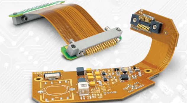
A Flex PCB, also known as a flexible printed circuit board, is a type of printed circuit board made with a flexible substrate material. This allows the board to bend and flex while still maintaining electrical connectivity between components. Flex PCBs provide many advantages over traditional rigid PCBs, especially in applications where flexibility, space savings, or durability are required. In this article, we will explore the key benefits of using flex PCB technology.
Key Advantages of Flex PCBs
Flexibility and Durability
The most obvious advantage of flex PCBs is their ability to flex and bend. The flexible substrate material allows the board to be folded, twisted, and contorted as needed to fit into tight or complex spaces. This makes them ideal for portable electronics, wearable devices, and medical equipment where a rigid board would not conform to the shape.
The flexibility also makes flex PCBs extremely durable against vibration, shock, and repeated motion. The material does not fatigue easily like a rigid board and is highly resistant to cracking. This is critical for dynamic applications like handheld devices. Flex PCBs can withstand millions of bend cycles without failure.
Space and Weight Savings
Because flex PCBs can be folded and bent, they require far less space than rigid boards. This allows for smaller and lighter-weight products, which is especially important for compact devices. The lack of bulky connectors found on rigid boards also contributes to space optimization.
For example, a rigid PCB may require multiple interconnected boards to route traces to various components in a tight space. A flex PCB can consolidate all of this into a single folded unit, saving significant real estate. Weight is also minimized by eliminating the need for heavy rigid components.
Increased Reliability
The flexible construction provides more reliable connectivity between board components versus soldered connections on rigid boards. The dynamic flexing motion does not crack solder joints or traces like what can happen over time with repeated stress on rigid boards.
This improved reliability also stems from having fewer overall solder joints and connections compared to rigid technology. With fewer solder points, there are fewer potential failure points in a flex PCB.
Simplified Assembly and Installation
Because flex PCBs can be bent and manipulated much like a cable, they simplify installation and assembly. Rigid boards often require careful placement along set axes, while flex boards can be dynamically routed as needed.
The simplified assembly lowers manufacturing costs and reduces the likelihood of assembly errors. Automated production is also easier with flex PCBs given their flexibility and durability.
Enhanced High Speed Signal Transmission
The physical properties of the flexible substrate provide excellent electrical performance advantages. Flex PCBs support higher frequency signals and faster timing due to lower dielectric loss. They also generate less noise than rigid boards.
This makes flex PCBs well-suited for high speed applications that require clean and efficient data transmission at fast rates. Things like routers, switches, and servers benefit greatly from the enhanced signal integrity of flex circuits.
Improved Thermal Management
The heat dissipation characteristics of flex PCBs are naturally better than rigid boards because the entire flexible substrate effectively becomes a large thermal pad. The motion also enhances airflow and cooling as the board moves.
This lends well to designs that must dissipate heat quickly from high power electronics or components. It also reduces the need for bulky aluminum heat sinks and complex cooling systems in some cases.
Design Flexibility
Flex PCBs enable more creative, customizable, and complex PCB solutions versus rigid technology. Things like irregular board shapes, 3D structuring, and embedded components are all possible by molding and shaping flex circuits. Rigid boards are far more constrained in their design options.
Flex PCBs can also be transparent, color tinted, or made with unique substrate materials like liquid crystal polymer. This permits additional design flexibility and customization ability compared to traditional boards.
Cost Savings
The combination of smaller size, lower weight, improved assembly, higher yields, faster production, and increased reliability ultimately makes flex PCBs more cost effective than rigid PCBs, especially at higher quantities.
Although rigid PCBs can be cheaper up front at prototype volumes, incorporation of flex technology pays dividends across the entire product lifecycle through significant savings in materials, assembly, installation, repairs, and servicing.
Flex PCB Applications
Some of the most common applications that benefit from using flex PCB technology include:
- Wearable electronics – smart watches, fitness trackers, health monitors, etc.
- Handheld/portable devices – cell phones, tablets, cameras, handheld gaming
- Automotive electronics – engine controls, dashboard displays, in-car entertainment
- Aerospace and military – guidance systems, communications, sensors
- Medical devices – hearing aids, implants, diagnostic equipment
- Robotics – arms, motors, sensors
- Instrumentation – probes, industrial control systems
Essentially any application where flexibility, space savings, weight reduction, or reliability are important considerations can benefit from utilizing flex PCBs instead of traditional rigid boards.
Flex PCB Materials and Construction
Flex PCBs get their flexible properties from the substrate material, which is usually a polyimide or polyester film. Common brands include Kapton and MYLAR. The thickness typically ranges from 12.5 to 100 micrometers.
The most widely used is a polyimide called Kapton, appreciated for its resilience at extreme temperatures and in demanding environments.
The traces are made from rolled annealed copper foil, with thicknesses between 12.5 to 35μm. The foil is laminated onto the substrate using adhesive bonding films and then etched to form the circuits.
Cover layers or solder masks are added to both sides for insulation and component stabilization. The surface finish protects the copper from oxidation and improves soldering. Common finishes include immersion tin, immersion silver, ENIG (electroless nickel immersion gold), and HASL (hot air solder leveled).
Flex PCBs usually have a minimum bend radius of at least 10 times the total board thickness. Creases or folds often include special treatment to avoid damage while bending sharply.
Flex PCB vs Rigid PCBs
While flex PCBs provide many advantages, traditional rigid PCBs still dominate the market. Here is a brief comparison between the two technologies:
Flex PCB
- Flexible and durable
- Small, thin, and lightweight
- Fewer solder joints
- Dynamic/repeated motion
- Efficient signal transmission
- Easier routing and assembly
- More expensive (initial prototyping)
Rigid PCB
- Sturdy support for components
- Larger sizes more economical
- Simpler board shapes
- Easy to prototype individually
- Assembly requires soldering
- Lower cost (initial prototyping)
In many cases, the two are used together, with flex PCBs connecting multiple rigid PCBs to create a complete circuit system. The integration maximizes the advantages of both technologies in one design.
Future of Flex PCBs
Flex PCB technology and material science is constantly improving. Here are some innovations and trends that will shape flex PCB development in the future:
- Extremely thin flexible circuits below 12.5μm
- Flex-rigid boards with rigid sections for mounting
- Embedded components for increased density
- Flexible substrates with stretchability and elasticity
- Transparent flex circuits using clear polyimide film
- Flexible electronics printed directly onto the substrate
- Multi-layer flex constructions exceeding 30 layers
- Improved high-frequency performance beyond 100GHz
- Direct integration of flex PCBs onto fabrics or polymer materials
- Increased use of automated assembly and additive manufacturing
Flex PCB Design Considerations
Here are some important tips when designing your own flex PCB:
- Minimize holes in the flex board to retain structural integrity
- Avoid sharp 90 degree bends where possible
- Use generous bend radii, at least 10X material thickness
- Analyze dynamic flexing with simulation and physical testing
- Ensure closure patterns to contain cracks and tears
- Add stiffeners or spacers between layers if needed
- Reduce loads on solder joints with adhesive mounting where possible
- Account for effects of flexing on electrical performance
- Thermally stress test at temperature extremes
- Develop in close collaboration with your flex PCB manufacturer
Conclusion
Flex PCBs provide indispensable advantages for electronics that require tight spaces, dynamic motion, rugged use, and high reliability. As technology pushes towards smaller, lighter, and more robust designs, flex circuits become increasingly critical solutions.
With their flexibility, durability, assembly benefits, efficiency, thermal performance, and reliability, flex PCBs will continue growing as a key enabling technology for cutting-edge devices and applications.
Frequently Asked Questions
What are the most common applications of flex PCBs?
Some of the most common flex PCB applications are wearable devices, medical equipment, aerospace systems, robotic systems, portable consumer electronics, instrumentation, and automotive electronics. Essentially any application where flexibility, space savings, durability and reliability are important factors.
How flexible can flex PCBs be?
Flex PCBs can be bent and twisted to quite extreme degrees. The minimum bend radius is usually at least 10 times the total board thickness, but some polyimide materials allow for very tight folds under 5X material thickness. Flex circuits can withstand millions of dynamic bend cycles without failure when properly designed.
Can components be mounted directly on flex PCBs?
Yes, components can be soldered directly onto flex PCBs. Adhesives are also often used to provide additional mechanical mounting support. Flexible adhesive circuits can also embed components between substrate layers. Careful design is needed around where components are placed to avoid damage from repeated flexing.
What are rigid-flex PCBs?
Rigid-flex PCBs integrate both rigid and flexible boards into one interconnected circuit solution. This allows rigid sections for component mounting along with flexible areas for dynamic routing and bending. Rigid-flex is an ideal way to maximize the advantages of both technologies in one design.
How are flex PCBs manufactured?
Flex PCB fabrication utilizes many of the same processes as rigid PCBs. The flexible substrate material is laminated with copper foil, photolithography is used to produce circuit traces, and various cover layers are added. Additional steps like controlled material thinning or specialized bending may be incorporated as well.


Leave a Reply