Introduction to ADS1115
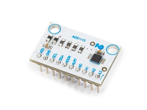
The ADS1115 is a high-precision, low-power, 16-bit analog-to-digital converter (ADC) that is commonly used with microcontrollers like Arduino for measuring analog signals. It offers excellent accuracy, programmable gain amplifier, and a wide operating voltage range, making it a popular choice for various applications such as data acquisition, sensor monitoring, and industrial control systems.
Key Features of ADS1115
-
High Resolution: The ADS1115 provides 16-bit resolution, allowing for precise measurement of analog signals. It can detect small changes in voltage, making it suitable for applications that require high accuracy.
-
Programmable Gain Amplifier (PGA): The built-in PGA allows you to adjust the gain of the ADC, enabling it to measure a wide range of input voltages. The gain can be set to 6.144V, 4.096V, 2.048V, 1.024V, 0.512V, 0.256V, or 0.256V/3.
-
Multiple Input Channels: The ADS1115 features four single-ended or two differential input channels, providing flexibility in connecting various sensors or analog signals.
-
I2C Interface: The ADS1115 communicates with the Arduino using the I2C protocol, which allows for easy integration and communication with other I2C devices on the same bus.
-
Low Power Consumption: With a typical supply current of only 150μA, the ADS1115 is suitable for battery-powered applications or projects where power efficiency is crucial.
-
Continuous or Single-Shot Conversion: The ADS1115 supports both continuous conversion mode and single-shot conversion mode, allowing you to choose between continuous monitoring or triggering conversions on-demand.
-
Comparator Function: The ADS1115 includes a built-in comparator that can be used to trigger an alert when the input signal crosses a specified threshold, enabling event-driven applications.
Interfacing ADS1115 with Arduino
To interface the ADS1115 with Arduino, you’ll need to make the necessary hardware connections and use the appropriate libraries to communicate with the ADC. Here’s a step-by-step guide:
Hardware Connections
- Connect the VCC pin of the ADS1115 to the 3.3V pin of the Arduino.
- Connect the GND pin of the ADS1115 to the GND pin of the Arduino.
- Connect the SCL pin of the ADS1115 to the SCL pin of the Arduino (A5 on Arduino Uno).
- Connect the SDA pin of the ADS1115 to the SDA pin of the Arduino (A4 on Arduino Uno).
- Connect the ADDR pin of the ADS1115 to GND for the default I2C address (0x48). If you need to use a different address, refer to the ADS1115 datasheet for the appropriate ADDR pin configuration.
Software Setup
-
Install the Adafruit ADS1X15 library in the Arduino IDE. You can do this by navigating to Sketch -> Include Library -> Manage Libraries, searching for “Adafruit ADS1X15,” and installing the library.
-
Include the necessary libraries in your Arduino sketch:
#include <Wire.h>
#include <Adafruit_ADS1X15.h>
- Create an instance of the Adafruit_ADS1115 class:
Adafruit_ADS1115 ads;
- In the
setup()function, initialize the ADS1115:
void setup() {
  ads.begin();
  // Set the gain and input voltage range
  ads.setGain(GAIN_ONE);
}
Reading Analog Values
To read analog values from the ADS1115, you can use the readADC_SingleEnded() function for single-ended inputs or the readADC_Differential_0_1(), readADC_Differential_2_3(), readADC_Differential_0_3(), or readADC_Differential_1_3() functions for differential inputs. Here’s an example:
void loop() {
  int16_t adc0 = ads.readADC_SingleEnded(0);
  float voltage0 = ads.computeVolts(adc0);

  Serial.print("AIN0: "); Serial.print(adc0); Serial.print(" ("); Serial.print(voltage0); Serial.println("V)");

  delay(1000);
}
In this example, we read the analog value from channel 0 using readADC_SingleEnded(0), compute the corresponding voltage using computeVolts(), and print the results to the serial monitor.

Configuring the ADS1115
The ADS1115 offers various configuration options to customize its behavior according to your application needs. Here are some key configuration settings:
Gain and Input Voltage Range
The ADS1115 has a programmable gain amplifier (PGA) that allows you to set the gain and adjust the input voltage range. The available gain settings and their corresponding input voltage ranges are as follows:
| Gain Setting | Input Voltage Range |
|---|---|
| GAIN_TWOTHIRDS | ±6.144V |
| GAIN_ONE | ±4.096V |
| GAIN_TWO | ±2.048V |
| GAIN_FOUR | ±1.024V |
| GAIN_EIGHT | ±0.512V |
| GAIN_SIXTEEN | ±0.256V |
To set the gain, use the setGain() function:
ads.setGain(GAIN_ONE);
Data Rate
The ADS1115 supports various data rates, allowing you to balance between conversion speed and noise performance. The available data rates are as follows:
| Data Rate | Samples per Second |
|---|---|
| RATE_ADS1115_8SPS | 8 |
| RATE_ADS1115_16SPS | 16 |
| RATE_ADS1115_32SPS | 32 |
| RATE_ADS1115_64SPS | 64 |
| RATE_ADS1115_128SPS | 128 |
| RATE_ADS1115_250SPS | 250 |
| RATE_ADS1115_475SPS | 475 |
| RATE_ADS1115_860SPS | 860 |
To set the data rate, use the setDataRate() function:
ads.setDataRate(RATE_ADS1115_128SPS);
Comparator and Alert Function
The ADS1115 includes a built-in comparator that can be used to trigger an alert when the input signal crosses a specified threshold. To configure the comparator and alert function:
- Set the comparator mode using
setComparatorMode():
ads.setComparatorMode(ADS1115_COMP_MODE_TRADITIONAL);
- Set the comparator polarity using
setComparatorPolarity():
ads.setComparatorPolarity(ADS1115_COMP_POL_ACTIVE_LOW);
- Set the comparator latch using
setComparatorLatch():
ads.setComparatorLatch(ADS1115_COMP_LATCH_DISABLED);
- Set the comparator queue using
setComparatorQueue():
ads.setComparatorQueue(ADS1115_COMP_QUEUE_NONE);
- Set the comparator thresholds using
setComparatorThreshold():
ads.setComparatorThreshold(1000, 3000);

Example Projects
Here are a few example projects that demonstrate the usage of ADS1115 with Arduino:
Project 1: Temperature Monitoring System
In this project, we’ll use the ADS1115 to measure the temperature using a thermistor and display the temperature on an LCD.
Components Required:
– Arduino Uno
– ADS1115
– Thermistor
– 10k resistor
– 16×2 LCD
– Breadboard and jumper wires
Circuit Diagram:
            Arduino Uno
            +-----------------+
            |                 |
            |           A4  o-|----SDA----- ADS1115
            |           A5  o-|----SCL-----      |
            |            5V o-|----VCC-----      |
            |           GND o-|----GND-----      |
            |                 |                   |
            +-----------------+               AIN0|-----Thermistor-----10k-----GND
                                                  |
                                                  +-----LCD (RS, EN, D4, D5, D6, D7)
Code:
#include <Wire.h>
#include <Adafruit_ADS1X15.h>
#include <LiquidCrystal.h>

Adafruit_ADS1115 ads;
LiquidCrystal lcd(12, 11, 5, 4, 3, 2);

void setup() {
  ads.begin();
  ads.setGain(GAIN_ONE);

  lcd.begin(16, 2);
  lcd.print("Temperature:");
}

void loop() {
  int16_t adc0 = ads.readADC_SingleEnded(0);
  float voltage = ads.computeVolts(adc0);
  float temperature = (voltage - 0.5) * 100;

  lcd.setCursor(0, 1);
  lcd.print(temperature);
  lcd.print(" C   ");

  delay(1000);
}
Project 2: Soil Moisture Monitoring System
In this project, we’ll use the ADS1115 to measure soil moisture using a capacitive Soil Moisture Sensor and send the data to a computer via serial communication.
Components Required:
– Arduino Uno
– ADS1115
– Capacitive soil moisture sensor
– Breadboard and jumper wires
Circuit Diagram:
            Arduino Uno
            +-----------------+
            |                 |
            |           A4  o-|----SDA----- ADS1115
            |           A5  o-|----SCL-----      |
            |            5V o-|----VCC-----      |
            |           GND o-|----GND-----      |
            |                 |                   |
            +-----------------+               AIN0|-----Soil Moisture Sensor
Code:
#include <Wire.h>
#include <Adafruit_ADS1X15.h>

Adafruit_ADS1115 ads;

void setup() {
  ads.begin();
  ads.setGain(GAIN_ONE);

  Serial.begin(9600);
}

void loop() {
  int16_t adc0 = ads.readADC_SingleEnded(0);
  float voltage = ads.computeVolts(adc0);
  float moisture = map(voltage, 0, 3.3, 0, 100);

  Serial.print("Soil Moisture: ");
  Serial.print(moisture);
  Serial.println("%");

  delay(1000);
}

Frequently Asked Questions (FAQ)
-
What is the maximum input voltage that the ADS1115 can handle?
The maximum input voltage that the ADS1115 can handle depends on the selected gain setting. With the highest gain setting (GAIN_SIXTEEN), the maximum input voltage range is ±0.256V. It’s important to ensure that the input voltage does not exceed the specified range to avoid damaging the ADC. -
Can I use the ADS1115 with 5V Arduino boards?
Yes, you can use the ADS1115 with 5V Arduino boards. The ADS1115 is a 3.3V device, but it is 5V tolerant on its I2C interface. However, make sure that the input voltage to the analog pins does not exceed the selected input voltage range. -
How can I connect multiple ADS1115 modules to the same Arduino?
To connect multiple ADS1115 modules to the same Arduino, you need to configure each module with a unique I2C address. The ADS1115 provides an ADDR pin that allows you to set the I2C address by connecting it to GND, VCC, SDA, or SCL. Refer to the ADS1115 datasheet for the corresponding address configurations. -
What is the difference between single-ended and differential inputs?
Single-ended inputs measure the voltage between an analog input pin and ground, while differential inputs measure the voltage difference between two analog input pins. Single-ended inputs are suitable for measuring signals referenced to ground, while differential inputs are useful for measuring small voltage differences or rejecting common-mode noise. -
How do I set the comparator threshold values?
To set the comparator threshold values, use thesetComparatorThreshold()function provided by the Adafruit ADS1X15 library. You need to specify the low threshold and high threshold values as parameters. For example,ads.setComparatorThreshold(1000, 3000)sets the low threshold to 1000 and the high threshold to 3000.
Conclusion
The ADS1115 is a versatile and high-precision ADC that offers excellent performance and flexibility for interfacing with Arduino. With its 16-bit resolution, programmable gain amplifier, and multiple input channels, it is suitable for a wide range of applications, including sensor monitoring, data acquisition, and industrial control systems.
By following the hardware and software setup guidelines provided in this article, you can easily integrate the ADS1115 with your Arduino projects. The Adafruit ADS1X15 library simplifies the process of configuring and reading analog values from the ADS1115, making it accessible for both beginners and experienced developers.
Remember to consider the input voltage range, data rate, and comparator settings when configuring the ADS1115 to ensure optimal performance and accuracy. With the ADS1115 and Arduino, you can create powerful and precise measurement systems tailored to your specific needs.
Happy coding and measuring with the ADS1115 and Arduino!


Leave a Reply