Introduction
Printed circuit boards (PCBs) are essential components in nearly all modern electronics. Traditionally, PCBs have been made from rigid materials like fiberglass. However, advances in materials science have led to the development of flexible PCBs made from transparent plastic substrates. These flexible transparent PCBs offer many advantages over traditional rigid PCBs. In this article, we’ll explore what transparent flexible PCBs are, their benefits, and some of their applications.
What are Flexible Transparent PCBs?

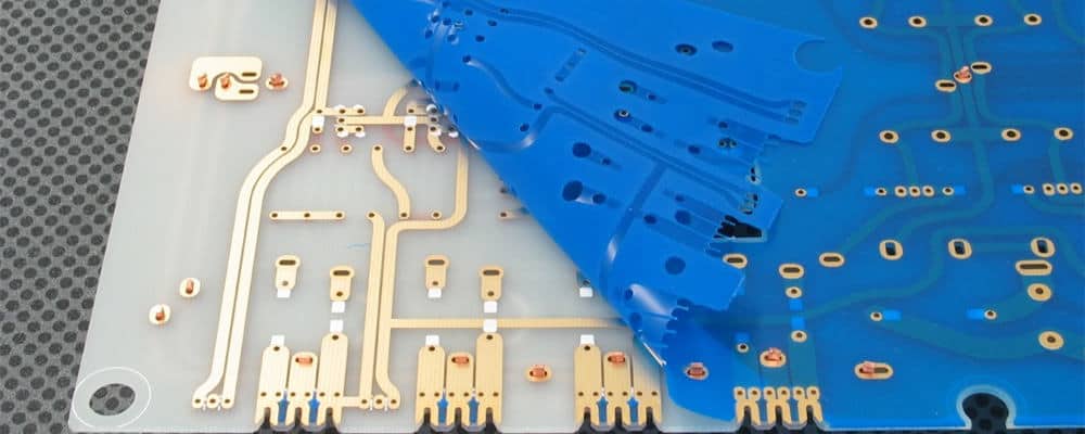
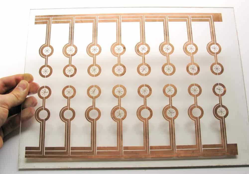
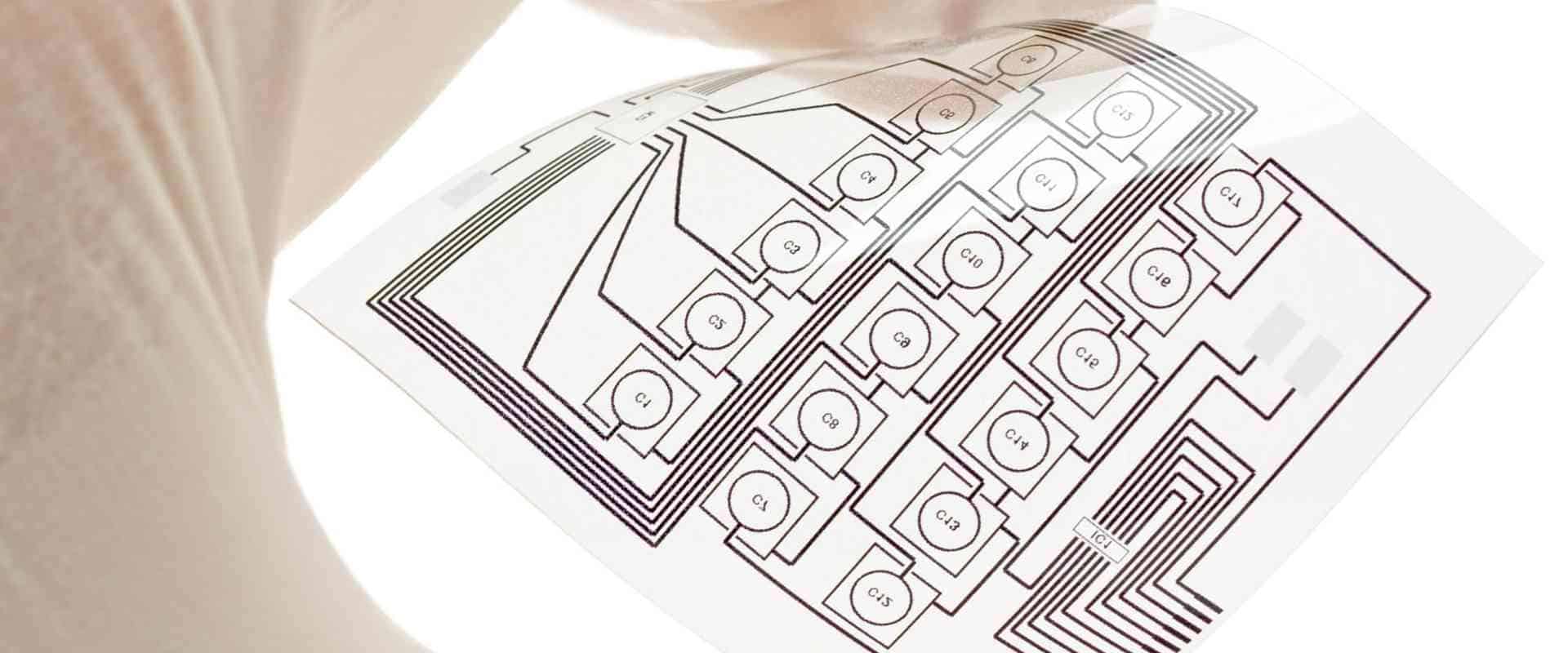
A flexible printed circuit board (FPCB) is a type of PCB made from flexible polymer materials like polyimide instead of rigid fiberglass. This allows the PCB to bend and flex without damage. Transparent flexible PCBs take this a step further by using clear transparent polymer substrates.
Some key properties of transparent flexible PCBs:
- Made from transparent polyimide or other clear polymer substrates
- Very thin, usually 25-100 μm thick
- Can be bent, folded, curved, twisted, etc. without damage
- Compatible with standard PCB manufacturing and assembly processes
- Allows integration of PCBs into curved or irregularly shaped devices
- Used in wearable electronics, medical devices, consumer products, and more
Common Materials for Flexible Transparent PCBs
Several types of polymers are used to manufacture the transparent substrates for flexible PCBs:
- Polyimide (PI) – Most common type; offers high heat resistance, chemical stability and mechanical strength
- Polyethylene terephthalate (PET) – Lower cost alternative, but less heat resistant
- Polyethylene naphthalate (PEN) – Similar properties as PET but can withstand higher temperatures
- Polycarbonate (PC) – Optically clear with moderate temperature resistance
- Cyclic olefin copolymer (COC) – Excellent optical clarity and relatively low cost
The choice of substrate material depends on the application requirements like operating temperature range, flexural endurance, dielectric properties, etc. Polyimide is the most versatile and commonly used.
Benefits of Flexible Transparent PCBs
Flexible transparent PCBs provide several important advantages that make them useful in many applications:
1. Design Flexibility
The ability to bend, fold and flex the PCB enables much more flexibility in product design. Transparent flexible PCBs can be integrated into irregular and curved surfaces, molded into 3D shapes, or bundled into tight spaces. This allows for more compact and ergonomic product designs.
2. Lightweight and Thin Profile
With transparent flexible PCBs, the substrate and traces can be extremely thin – typically 25 to 100 μm. This results in a very lightweight and low profile PCB that adds minimal size and weight to a product.
3. Highly Durable
The flexible material makes the PCBs very durable against vibration, shock and flexing stresses. Polymer substrates like polyimide provide excellent mechanical strength and flex life. This makes them ideal for dynamic applications.
4. Improved Signal Transmission
The thin, lightweight nature of the flexible PCB material results in shorter trace lengths and reduced dielectric constant. This improves signal speed and integrity compared to thicker rigid PCB substrates.
5. Optical Transparency
The clear see-through substrate enables integration of PCBs with display technologies, transparent conductors, sensors and other optical components. This is useful for heads-up displays, touch screens and other transparent electronics.
6. Biocompatibility
Many of the transparent polymer substrates offer high biocompatibility. This allows their use in medical devices and wearable electronics that interface with the human body.
7. Cost Effective High Volume Production
Flexible PCBs can leverage highly efficient roll-to-roll processing methods. This makes their high volume manufacturing very cost effective compared to rigid PCB fabrication.
Applications of Flexible Transparent PCBs
With their unique set of advantages, transparent flexible PCBs are enabling many new applications:
Wearable Electronics
The light weight and flexibility is ideal for integrating PCBs into wearable products like smart watches, fitness trackers, AR/VR glasses etc. Polyimide’s biocompatibility also makes it safe for skin contact applications.
Medical Devices
Transparent flex PCBs allow diagnostic and monitoring medical devices to be small, lightweight and contour to the body. Integration with biosensors provides functionally integrated solutions.
Consumer Electronics
Curved screens, rollable displays and foldable phones are enabled by flexible PCBs that can bend dynamically. Light weight and small PCBs also support slimmer product designs.
Automotive Displays
Dashboard screens, touch sensors and heads-up displays use flexible PCBs that conform to sloped and curved windshields and interior surfaces.
IoT and Robotics
The tight space constraints in small connected devices and robotics benefit from thin profile flexible PCBs. They’re easy to integrate with sensors, antennae and other components.
Flexible Heaters
Transparent polyimide is an excellent flexible heater element when integrated with printed heating elements. This is ideal for defoggers, heated windows, warming clothes etc.
Soft Robotics
Robots based on inflatable or flexible bodies can integrate control circuits on transparent flex PCBs. These provide sensing and control electronics seamlessly integrated into the deformable robotic system.
Flex PCB Design Considerations

Designing transparent flexible PCBs requires paying attention to some unique considerations:
- Flexible substrate – Most designs will use polyimide but polyethylene terephthalate (PET) can also be used for very lightweight low-cost boards.
- Conductor thickness – Copper traces are typically very thin (5 to 35 μm) to accommodate frequent flexing. Thicker copper (25-70 μm) is sometimes used for high current traces.
- Stiffener support – Rigid stiffeners or spacers may be used selectively along with flexible zones to provide load bearing strength when needed.
- Dynamic flexing – Minimize conductor paths across areas that will undergo frequent dynamic bending. This reduces the risk of work hardening and fracture.
- Bending radius – Traces should not bend tighter than the minimum bend radius. This is typically defined as 8 to 10 times the board thickness.
- Layer stackup – 1 to 6 conductive layers are typical. Careful alignment helps avoid shear stresses between layers during flexing.
- Component mounting – Components are surface mounted using conductive adhesive or small solder points. Avoid large or heavy components in highly dynamic areas.
Prototyping and design verification on actual flex PCB materials is highly recommended due to the unique mechanical properties involved.
Flex PCB Design Tools
Specialized PCB layout tools like Altium Designer, Cadence Allegro and Mentor Xpedition include comprehensive flex PCB design rule checks and modeling capabilities to address these requirements.
The Future of Flexible PCBs
Flexible PCB technology will continue opening up new possibilities in electronic product development. Here are some promising areas that are emerging:
- Printed electronics – Flexible PCBs with printed conductors enable efficient roll-to-roll manufacturing of electronic circuits. This supports high volume production of affordable flexible electronics.
- Stretchable electronics – Conductive traces can be made stretchable through novel geometries and materials. This allows flexible PCBs to maintain integrity even when undergoing elongation.
- Logic Fabrication – Large area flexible PCBs with printed transistors support new fabrication approaches for high performance flexible logic processors and memory.
- E-textiles – Low cost flexible PCBs combined with conductive yarns and textile fabrication methods will enable an new generation of smart fabric technologies.
- Flexible Displays – Flexible OLED and LCD display technologies require compatible flexible PCB backplanes to control and drive the displays.
- 3D Structured Flex – Flexible circuits can be folded and formed into complex 3D structures for space saving compact electronics and sensors.
Conclusion
Flexible transparent PCBs represent an important enabling technology that allows electronics to be integrated with the physical world in ways never before possible. Their unique mechanical properties combined with unhindered optical transparency will continue opening up new and exciting applications that shape the future of electronics.
Frequently Asked Questions
What are the main advantages of transparent flexible PCBs?
The key advantages are design flexibility, thin/lightweight construction, durability, improved signal transmission, optical transparency, biocompatibility, and cost-effective high-volume production.
What are the typical materials used for the flexible substrate?
Polyimide is the most common flexible PCB substrate, but PET and PEN are also used. Polycarbonate and COC provide the greatest optical clarity.
How thin can flexible PCBs be fabricated?
Flexible PCBs can be extremely thin, ranging from 25 to 100 microns (0.001 to 0.004 inches). Rigid sections or stiffeners may be thicker.
What are some key design considerations for flex PCBs?
Considerations include conductor thickness, dynamic flex zones, bend radius, layer alignment, component mounting, and utilizing design tools with flex PCB modeling and rule checks.
What emerging applications will benefit from flexible transparent PCB technology?
Key emerging applications include wearable electronics, e-textiles, flexible displays, stretchable circuits, printed electronics, flexible sensors, and 3D structured electronics.


Leave a Reply