What are Zero-Crossing Detectors?
Zero-crossing detectors are electronic circuits that detect the point at which an alternating current (AC) signal crosses the zero voltage level. In other words, they identify the moment when the voltage waveform transitions from positive to negative, or vice versa. This information is essential for controlling the timing of switching devices, such as solid-state relays (SSRs) or triacs, which are commonly used in power control applications.
How do Zero-Crossing Detectors Work?
The basic principle behind zero-crossing detection is to compare the input AC signal with a reference voltage, typically ground (0V). When the input signal crosses the reference voltage, the detector generates a pulse or a digital signal that indicates the zero-crossing event. This output signal can then be used to trigger the switching of power control devices at the optimal moment, minimizing electrical disturbances and reducing stress on the components.
A typical zero-crossing detector circuit consists of the following components:
-
Input Conditioning Stage: This stage is responsible for scaling and filtering the input AC signal to ensure proper operation of the detector. It may include voltage dividers, low-pass filters, or isolation transformers to remove high-frequency noise and protect the circuit from high voltages.
-
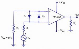
Comparator: The comparator is the heart of the zero-crossing detector. It compares the conditioned input signal with the reference voltage and generates a digital output signal when the input crosses the reference. The comparator can be implemented using operational amplifiers (op-amps) or dedicated comparator ICs.
-
Output Stage: The output stage converts the comparator’s digital signal into a form suitable for driving the power control devices. This may involve level-shifting, pulse shaping, or isolation, depending on the specific requirements of the application.
Benefits of Using Zero-Crossing Detectors
Incorporating zero-crossing detectors in electronic equipment offers several key benefits:
-
Reduced Electromagnetic Interference (EMI): By switching power control devices at the zero-crossing points, the generation of high-frequency transients and electromagnetic noise is minimized. This helps in meeting EMI regulations and prevents interference with other electronic devices.
-
Improved Power Quality: Zero-crossing detection ensures that power switching occurs at the optimal moment, reducing harmonic distortion and improving the overall power quality of the system. This is particularly important in applications involving sensitive electronic loads or power factor correction.
-
Extended Equipment Lifespan: By minimizing electrical stress on the components, zero-crossing detectors help extend the lifespan of power control devices and the electronic equipment they protect. This translates to reduced maintenance costs and improved system reliability.
-
Simplified Control Logic: With zero-crossing detection, the control logic for power switching can be simplified. The detector provides a clean, synchronized signal that can be easily integrated into the control circuitry, eliminating the need for complex timing calculations or phase-angle control algorithms.

Applications of Zero-Crossing Detectors
Zero-crossing detectors find applications in a wide range of electronic systems, including:
-
Home Appliances: In devices such as light dimmers, temperature controllers, and motor speed controls, zero-crossing detectors enable smooth and efficient power regulation while minimizing electrical noise.
-
Industrial Automation: Zero-crossing detectors are extensively used in industrial control systems, such as programmable logic controllers (PLCs) and process control equipment, to ensure precise and reliable power switching for machinery and actuators.
-
Power Electronics: In power converters, inverters, and uninterruptible power supplies (UPS), zero-crossing detection is employed for synchronization and control of power switching devices, improving efficiency and reducing harmonics.
-
Lighting Control: Zero-crossing detectors are essential components in lighting control systems, enabling smooth dimming and flicker-free operation of LED and fluorescent lights.
-
HVAC Systems: In heating, ventilation, and air conditioning systems, zero-crossing detectors are used to control the power switching of compressors, fans, and heating elements, optimizing energy efficiency and maintaining stable temperature control.

Selecting the Right Zero-Crossing Detector
When choosing a zero-crossing detector for a specific application, several factors should be considered:
-
Input Voltage Range: The detector must be compatible with the input AC voltage range of the system. Common voltage ranges include 120V, 230V, and 480V, but there are also detectors available for low-voltage applications.
-
Output Signal Characteristics: The output signal of the detector should be suitable for interfacing with the power control devices and control circuitry. Factors such as output voltage level, current drive capability, and response time should be taken into account.
-
Isolation: In applications involving high voltages or where electrical isolation is required, optically isolated zero-crossing detectors are preferred. These detectors provide galvanic isolation between the input and output stages, enhancing safety and reliability.
-
Noise Immunity: The detector should have adequate noise immunity to operate reliably in electrically noisy environments. Features such as hysteresis, filtering, and shielding can improve the detector’s resilience to noise and interference.
-
Package and Mounting: The physical package and mounting options of the detector should be suitable for the intended application. Surface-mount, through-hole, and panel-mount packages are commonly available, allowing for flexibility in circuit board design and installation.

Implementing Zero-Crossing Detection in Electronic Systems
Integrating zero-crossing detection into an electronic system involves the following steps:
-
Circuit Design: The zero-crossing detector circuit is designed based on the specific requirements of the application, taking into account factors such as input voltage range, output signal characteristics, and isolation needs.
-
Component Selection: The appropriate components, including the comparator, input conditioning stage, and output stage, are selected based on the circuit design and performance requirements.
-
PCB Layout: The circuit is laid out on a printed circuit board (PCB), following best practices for signal integrity, noise reduction, and power management. Proper grounding, shielding, and routing techniques are employed to minimize interference and ensure reliable operation.
-
Firmware Development: If the zero-crossing detector is part of a microcontroller-based system, firmware is developed to process the detector’s output signal and control the power switching devices accordingly. The firmware should include necessary timing and synchronization routines to ensure accurate and efficient power control.
-
Testing and Validation: The implemented zero-crossing detection system is thoroughly tested and validated under various operating conditions to ensure its functionality, reliability, and compliance with relevant standards and regulations.
Frequently Asked Questions (FAQ)
-
What is the purpose of a zero-crossing detector?
A zero-crossing detector is used to identify the point at which an alternating current (AC) signal crosses the zero voltage level. This information is crucial for controlling the timing of power switching devices, such as solid-state relays or triacs, to minimize electrical disturbances and protect sensitive electronic equipment. -
How does a zero-crossing detector work?
A zero-crossing detector compares the input AC signal with a reference voltage, typically ground (0V). When the input signal crosses the reference voltage, the detector generates a pulse or a digital signal that indicates the zero-crossing event. This output signal is then used to trigger the switching of power control devices at the optimal moment. -
What are the benefits of using zero-crossing detectors in electronic systems?
The benefits of using zero-crossing detectors include reduced electromagnetic interference (EMI), improved power quality, extended equipment lifespan, and simplified control logic. By switching power control devices at the zero-crossing points, electrical noise and stress on components are minimized, leading to improved system reliability and efficiency. -
What factors should be considered when selecting a zero-crossing detector?
When selecting a zero-crossing detector, factors such as input voltage range, output signal characteristics, isolation requirements, noise immunity, and package/mounting options should be considered. The detector must be compatible with the specific requirements of the application and the overall electronic system. -
How is zero-crossing detection implemented in an electronic system?
Implementing zero-crossing detection involves designing the detector circuit, selecting appropriate components, laying out the circuit on a PCB, developing firmware (if applicable), and thoroughly testing and validating the system. Proper design and implementation practices should be followed to ensure reliable and efficient operation of the zero-crossing detection system.
Conclusion
Zero-crossing detectors play a vital role in protecting sensitive electronic equipment from electrical disturbances and ensuring efficient power control. By detecting the zero-crossing points of AC signals, these devices enable precise timing of power switching, reducing electromagnetic interference, improving power quality, and extending equipment lifespan.
When incorporating zero-crossing detection into an electronic system, careful consideration should be given to factors such as input voltage range, output signal characteristics, isolation requirements, and noise immunity. Proper circuit design, component selection, PCB layout, and firmware development are essential for achieving optimal performance and reliability.
As electronic systems continue to advance and become more complex, the importance of zero-crossing detectors in protecting sensitive equipment and ensuring smooth operation will only continue to grow. By understanding the principles and applications of zero-crossing detection, engineers and designers can effectively integrate these devices into their systems, ultimately leading to more robust, efficient, and reliable electronic solutions.


Leave a Reply