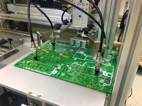
What is PCB Milling?
PCB milling is a process of creating printed circuit boards (PCBs) using a specialized milling machine. This process involves removing unwanted copper from a copper-clad board to create the desired circuit pattern. PCB milling is an alternative to traditional PCB fabrication methods, such as etching, and offers several advantages, including faster prototyping, lower costs for small-batch production, and the ability to create complex designs.
Advantages of PCB Milling
- Rapid prototyping: PCB milling allows for quick iterations of PCB designs, enabling faster testing and refinement of prototypes.
- Cost-effective for small batches: For low-volume production, PCB milling is often more economical than traditional PCB fabrication methods.
- Complex designs: Milling machines can create intricate patterns and shapes that may be difficult or impossible to achieve with other methods.
- In-house production: With a PCB milling machine, you can create PCBs in-house, reducing lead times and dependency on external manufacturers.
How PCB Milling Works
The PCB Milling Process
- Design: Create your PCB design using electronic design automation (EDA) software, such as KiCad, Eagle, or Altium Designer.
- CAM file generation: Export your design as a computer-aided manufacturing (CAM) file, typically in Gerber or G-code format.
- Machine setup: Load the CAM file into the PCB milling machine’s software and configure the milling parameters, such as tool size, feed rate, and depth of cut.
- Board preparation: Cut your copper-clad board to the desired size and secure it to the milling machine’s bed.
- Milling: Start the milling process, which will remove unwanted copper from the board, leaving behind the desired circuit pattern.
- Cleaning: Remove any debris or dust from the milled board using compressed air or a brush.
- Inspection: Visually inspect the milled board for any defects or errors.
- Assembly: Solder components onto the milled PCB to complete your project.
PCB Milling Equipment
To get started with PCB milling, you’ll need the following equipment:
- PCB milling machine: A specialized CNC machine designed for milling PCBs, such as the Bantam Tools Desktop PCB Milling Machine or the Prometheus PCB Milling Machine.
- Copper-clad boards: Blank PCBs with a layer of copper on one or both sides, available in various sizes and thicknesses.
- Milling bits: Carbide or diamond-coated bits specifically designed for PCB milling, available in different diameters for various trace widths and hole sizes.
- Software: EDA software for designing your PCBs and CAM software for generating milling files and controlling the milling machine.
- Safety equipment: Safety glasses, dust mask, and gloves to protect yourself during the milling process.

PCB Design Considerations for Milling
When designing PCBs for milling, there are several factors to consider to ensure the best results:
- Trace width: Milling machines have limitations on the minimum trace width they can create. Ensure your design adheres to the capabilities of your specific machine.
- Clearance: Provide adequate clearance between traces and components to avoid short circuits and facilitate easier soldering.
- Drill sizes: Consider the available drill bit sizes when designing holes for through-hole components or vias.
- Material thickness: Choose the appropriate copper-clad board thickness for your project, taking into account the depth of cut your milling machine can achieve.
- Gerber file compatibility: Ensure your EDA software can export Gerber files compatible with your milling machine’s software.

Tips for Successful PCB Milling
- Double-check your design: Before milling, carefully review your PCB design for any errors or potential issues.
- Use the correct milling bits: Select the appropriate milling bit size for your design and material to ensure clean, accurate cuts.
- Calibrate your machine: Regularly calibrate your milling machine to maintain precision and accuracy.
- Secure your board: Ensure your copper-clad board is securely fastened to the milling machine’s bed to prevent shifting during the milling process.
- Test your design: After milling, test your PCB for continuity and correct functionality before assembling components.

Troubleshooting Common PCB Milling Issues
| Issue | Possible Causes | Solutions |
|---|---|---|
| Inaccurate milling | – Incorrect milling bit size – Machine calibration issues – Loose or shifting board |
– Use the correct milling bit for your design – Recalibrate your milling machine – Securely fasten the board to the machine bed |
| Broken milling bits | – Excessive feed rate – Incorrect depth of cut – Dull or worn bits |
– Reduce feed rate – Adjust depth of cut – Replace milling bits regularly |
| Incomplete cuts | – Insufficient depth of cut – Dull milling bits – Incorrect CAM file settings |
– Increase depth of cut – Replace milling bits – Review and adjust CAM file settings |
| Rough or burr-filled edges | – Excessive feed rate – Dull milling bits – Incorrect depth of cut |
– Reduce feed rate – Replace milling bits – Adjust depth of cut |
Frequently Asked Questions (FAQ)
-
Q: What is the minimum trace width I can achieve with PCB milling?
A: The minimum trace width depends on your specific milling machine and the milling bits used. Generally, most machines can achieve trace widths as small as 0.2mm (8mil) or less. -
Q: Can I mill double-sided PCBs?
A: Yes, you can mill double-sided PCBs by milling one side, flipping the board over, and milling the other side. However, ensure proper alignment when flipping the board to maintain accuracy. -
Q: How long does it take to mill a PCB?
A: The milling time depends on the complexity of your design, the size of the board, and the milling machine’s speed. Simple designs can take a few minutes, while more complex boards may take an hour or more. -
Q: Can I use regular end mills for PCB milling?
A: While regular end mills may work for some applications, it’s recommended to use milling bits specifically designed for PCB milling. These bits are typically made of carbide or diamond-coated material and have the appropriate flute geometry for cleanly cutting copper and PCB substrates. -
Q: How do I choose the right copper-clad board for my project?
A: When selecting a copper-clad board, consider the following factors: - Thickness: Choose a board thickness appropriate for your project’s mechanical requirements and your milling machine’s capabilities.
- Copper weight: Copper-clad boards are available in various copper weights, typically ranging from 0.5oz to 2oz per square foot. Heavier copper weights are better for high-current applications but may require more milling time.
- Material: FR-4 is the most common PCB substrate material, but other options like aluminum or flexible substrates are available for specific applications.
Conclusion
PCB milling offers a fast, cost-effective, and versatile method for creating custom printed circuit boards. By understanding the milling process, design considerations, and best practices, you can successfully mill your own PCBs for prototyping and small-batch production. With the right equipment, software, and techniques, PCB milling can be a valuable addition to your electronics design and fabrication toolkit.


Leave a Reply